You can use a resistor or capacitor. The resistor could be a 1k. The capacitor a 0.1uF to 0.1uF.
The cap would be connected gate to source. The resistor would be gate to source then gate to drain.
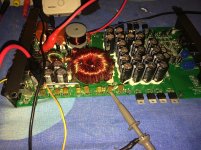
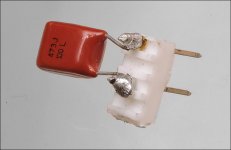
For this test, I generally use a 0.047uF capacitor on a header so I can drop it into each location and test all drive circuits up to the FET.
The cap would be connected gate to source. The resistor would be gate to source then gate to drain.
For this test, I generally use a 0.047uF capacitor on a header so I can drop it into each location and test all drive circuits up to the FET.
Picture of gate drive without the FETS in.
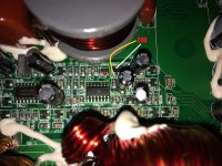
I found maybe something interesting.
D707 = F3 is showing short between the two legs - marked in red
D708 = UX is showing ~248 in diode mode between marked leg
Should be those replaced ?!
I found maybe something interesting.
D707 = F3 is showing short between the two legs - marked in red
D708 = UX is showing ~248 in diode mode between marked leg
Should be those replaced ?!
Attachments
Perry You are the man 
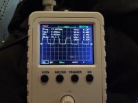
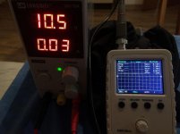
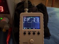
Loaded the drive circuit with 0.047uf film caps...
One of the bank is straight DC, the other one has some gate drive, not exactly perfect...
So the drive transistors are dead ? If i'm being correct TL494-->driver/buffer transistors --> gate resistors --> PS mosfets...
So i doubt it's the TL494, I've never seen even one failed...
Attachments
The 494s sometimes fail but it's not always a catastrophic failure. In some instances, the regulators go out of tolerance or they won't oscillate at the right frequency.
You can load like you did but you don't need to take that much time. If you just check each location by inserting the cap and looking for a change from the perfect square wave, it's quicker (less than a minute). I solder the cap to a header which makes it a bit easier than the tiny leads.
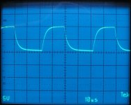
The image below is what you can expect from a loaded drive circuit beyond the gate resistors.
One of your drive circuits is likely OK. The one with excessive DC likely has a defective PNP driver (assuming it uses transistors, I don't have the diagram). The NPN drivers generally survive but should be checked, at the very least.
You can load like you did but you don't need to take that much time. If you just check each location by inserting the cap and looking for a change from the perfect square wave, it's quicker (less than a minute). I solder the cap to a header which makes it a bit easier than the tiny leads.
The image below is what you can expect from a loaded drive circuit beyond the gate resistors.
One of your drive circuits is likely OK. The one with excessive DC likely has a defective PNP driver (assuming it uses transistors, I don't have the diagram). The NPN drivers generally survive but should be checked, at the very least.
Attachments
You can load like you did but you don't need to take that much time. If you just check each location by inserting the cap and looking for a change from the perfect square wave, it's quicker (less than a minute). I solder the cap to a header which makes it a bit easier than the tiny leads.
- Status
- This old topic is closed. If you want to reopen this topic, contact a moderator using the "Report Post" button.
- Home
- General Interest
- Car Audio
- Pioneer GM-D9601 burnt caps value ?!