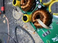
I have a Kicker CXA 1800.1 amp that wants to pull high current. I have the current limited via a 100w 2 ohm resistor to keep from letting the magic smoke out.
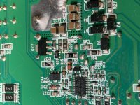
There is what looks like a 10 ohm SMD resistor heating up on the bottom of the main board with current limited power applied and an SMD transistor close by that test shorted across the two bottom legs with power removed. I think the code on top of the transistor reads 5BW. The transistor is marked Q20 on the board. When I look it up I get BC807 as the transistor. There are many different versions for this transistor listed on mouser. Does it matter which one I choose?
I was also wondering what caused this transistor to fail. I’m not sure what it’s function is in the circuit. I have checked the other components in the vicinity of the shorted transistor and they check out fine. Is there something further up or down the circuit I need to check?
David
Attachments
Last edited:
Q20-BC817, Q20-BCP53, IC8-LM393 make up the Hi-Level Turn-On circuit. The alternative Turn on when there is no remote line from head unit.
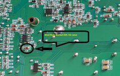
R38-10 ohm is tied to an 18 volt zener ZD9 which is most likely shorted. You will find IC8 on the other side of board. The Zener is there to protect IC8 if the voltage exceeds 18 volts. R38 inputs the 12 volt battery terminal voltage and outputs a Reg 12v and is burning because its looking into a dead short.
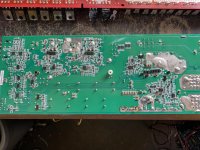
If you post a good quality picture of the whole board I can help you navigate the board. You may find other issues that I can help with also.
R38-10 ohm is tied to an 18 volt zener ZD9 which is most likely shorted. You will find IC8 on the other side of board. The Zener is there to protect IC8 if the voltage exceeds 18 volts. R38 inputs the 12 volt battery terminal voltage and outputs a Reg 12v and is burning because its looking into a dead short.
If you post a good quality picture of the whole board I can help you navigate the board. You may find other issues that I can help with also.
Attached is a pic of the ZD9-18v zener, which is more then likely shorted. The link below for mouser is a good replacement
ZM4746A L0G Taiwan Semiconductor | Mouser
The BC817 any SOT-23 package should work. The link below is an On Semiconductor product from Mouser.
BC817-40WT1G ON Semiconductor | Mouser
ZM4746A L0G Taiwan Semiconductor | Mouser
The BC817 any SOT-23 package should work. The link below is an On Semiconductor product from Mouser.
BC817-40WT1G ON Semiconductor | Mouser
Attachments
Another link for the BC807. I'm not sure about what the package size. This one uses an SOT-23 The BC817 showed an SC−70/SOT−323 package.They may be similar,and I'm not sure what the footprint for the CXA18001 will accommodate. A quick google search will give you to specs for each footprint to compare.
BC807-40LT1G ON Semiconductor | Mouser
BC807-40LT1G ON Semiconductor | Mouser
Ok. I changed the components that were discussed earlier on this amp and it’s still drawing high amps. I did find that C93 tests shorted across it and on each side to ground. I’m not sure of the value of this cap and I’m not sure what else could be wrong. None of the components on the top side of the board are shorted so I’ve been primarily focused on the bottom of the board where the drivers and ICs are located.
David
David
After reviewing my post #2 I realized my mistake. The Q20-BCP53 I've highlighted should be Q22-BCP53. Also, Q20-BC817 should be a BC807
My apologize!!
"Q20-BC817, Q20-BCP53, IC8-LM393 make up the Hi-Level Turn-On circuit. The alternative Turn on when there is no remote line from head unit."
This may be why you are still having issues. To be safe you may want to replace Q20-BC807,Q22-BCP53 and IC8-LM393 and check the resistors R80-4.7 ohm R81-20kohm. Also, be sure to check ZD9-18volt zener.
I checked components mentioned in post 9
R27 check out at 10ohms
C93 and C94 give me a reading of 100nf out of circuit
C93 and C94 test shorted in circuit across them and on each side to ground.
I changed all of the components mentioned in post 10 and the amp still pulls high amps and tries to burn R38 10ohm resistor.
David
R27 check out at 10ohms
C93 and C94 give me a reading of 100nf out of circuit
C93 and C94 test shorted in circuit across them and on each side to ground.
I changed all of the components mentioned in post 10 and the amp still pulls high amps and tries to burn R38 10ohm resistor.
David
I had to remove the power supply mosfets to get the amp to stop pulling high amps.
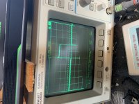
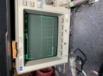
This is the drive in the power supply.
Scope is set to 5v/div and 500n/s DC coupled probe grounded to negative terminal.
In the output section I’m not seeing any drive. On the pads without the ceramic cap, I’m seeing about 4 volts DC on the two outside pads for the mosfets and 14 volts DC on the center pad for the mosfets.
On the pads with the ceramic cap I’m seeing ground on the outside pads at 0 volts DC and about 4 volts DC on the center pads.
Attachments
I had to remove the power supply mosfets to get the amp to stop pulling high amps.
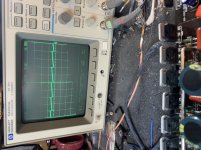
This is the drive in the power supply.
Scope is set to 5v/div and 500n/s DC coupled probe grounded to negative terminal.
In the output section I’m not seeing any drive. On the pads without the ceramic cap, I’m seeing about 4 volts DC on the two outside pads for the mosfets and 14 volts DC on the center pad for the mosfets.
What ceramic caps are you referring to, and are you trying to see Drive w/o Power Supply Mosfets?
On the pads with the ceramic cap I’m seeing ground on the outside pads at 0 volts DC and about 4 volts DC on the center pads.
Okay, this looks fine. The Power Supply appears to be working there must be something outside of the power supply causing a high current draw. This may be the Hi Level turn on circuit or the regulated power supply attached to the resistor that wants to burn up R38-10 ohm. I reviewed the thread and wanted to be clear that the following post was applied.
After reviewing my post #2 I realized my mistake. The Q20-BCP53 I've highlighted should be Q22-BCP53. Also, Q20-BC817 should be a BC807
This may be why you are still having issues. To be safe you may want to replace Q20-BC807,Q22-BCP53 and IC8-LM393 and check the resistors R80-4.7 ohm R81-20kohm. Also, be sure to check ZD9-18volt zener.
- Status
- This old topic is closed. If you want to reopen this topic, contact a moderator using the "Report Post" button.
- Home
- General Interest
- Car Audio
- Kicker CXA 1800.1 pulls high amps