Hi guys
i have a mitsubishi lancer 2016 and i have knowledge about electronics but this is gives me a headache
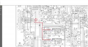
try to take out the rca line from the headunit follow the lines and read the manual service of the same headunit
the first i do is solder Right, Left and Ground before reach to the IC audio amp
but there are 3 grounds!!!! and i dont know which select for the ground of the RCA. There is
AC-GND
PRE-GND (Is actually use for the rca, is this right?)
TAB
1.- I supposed is the PRE-GND the correct ground for the rca cable right???
2.- i do that and “works” but when i start the car the amplifier make a kick of DC from the rca (just 1 kick, after that works normally) and the amplifier get noise from the motor and this never happen when i use the headunit whit normal use (without external amp)
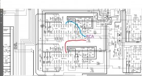
3.- i try to go more further doing this... i attached my rcas before some resistors and capacitors, even before the IC Audio Variable Volume to get more quality in the audio and i do this.
i make this kind of capacitors between ground/rca lines and series to reduce DC and the engine noise but didnt work IMAGE ATTACHED
but now is worst the dc. if i I lower or raise the glasses of the car get dc in the rcas and sounds very bad.
is not the amplifier, mine is a ORION xtr 500/2 and i try with a JL AUDIO 300/4 and do the same
4.- what is wrong? the value of capacitors and or the type of capacitors? i use ceramic between the lines and ground (i use Pre-GND LINE) to avoid engine noise and the electrolitic in series to eliminate the dc (gold capacitor shamwa)
any ideas my friend to get my project fully working without engine noise and no dc
thank you!
i have a mitsubishi lancer 2016 and i have knowledge about electronics but this is gives me a headache
try to take out the rca line from the headunit follow the lines and read the manual service of the same headunit
the first i do is solder Right, Left and Ground before reach to the IC audio amp
but there are 3 grounds!!!! and i dont know which select for the ground of the RCA. There is
AC-GND
PRE-GND (Is actually use for the rca, is this right?)
TAB
1.- I supposed is the PRE-GND the correct ground for the rca cable right???
2.- i do that and “works” but when i start the car the amplifier make a kick of DC from the rca (just 1 kick, after that works normally) and the amplifier get noise from the motor and this never happen when i use the headunit whit normal use (without external amp)
3.- i try to go more further doing this... i attached my rcas before some resistors and capacitors, even before the IC Audio Variable Volume to get more quality in the audio and i do this.
i make this kind of capacitors between ground/rca lines and series to reduce DC and the engine noise but didnt work IMAGE ATTACHED
but now is worst the dc. if i I lower or raise the glasses of the car get dc in the rcas and sounds very bad.
is not the amplifier, mine is a ORION xtr 500/2 and i try with a JL AUDIO 300/4 and do the same
4.- what is wrong? the value of capacitors and or the type of capacitors? i use ceramic between the lines and ground (i use Pre-GND LINE) to avoid engine noise and the electrolitic in series to eliminate the dc (gold capacitor shamwa)
any ideas my friend to get my project fully working without engine noise and no dc
thank you!
Attachments
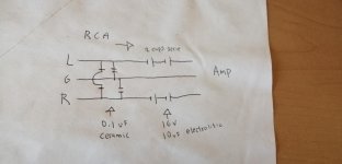
You don't need the 0.1 bypass caps.
You need to install a 100k pulldown resistor after the DC blocking caps.
You will probably not have enough signal doing it this way but you shouldn't have noise problems.
Hi sir babin thanks for answer
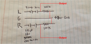
is correct like this. in the picture
2 caps golden serie 10uf 16v in each signal
100k resistor in each line signal
the ground Pre GND Is the correct?
thank you
Attachments
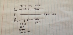
You only need one capacitor for each channel, even McIntosh used polarized caps there instead of non polar.
got it
thank you i will use just 1 capacitor by line
See attached.
To add to #4, the caps don't need to be bipolar if there is DC on the input to them that will always be positive voltage.
thank you some much Sir Babin
i will.do it.like you draw it
- Status
- This old topic is closed. If you want to reopen this topic, contact a moderator using the "Report Post" button.
- Home
- General Interest
- Car Audio
- help stock headunit dc on rca