Yes I know it's not in protect at the moment I took the rail caps out do you want me to take the measurements again with it in protect.
The previous Gate Drive signals I sent you pics of was with the amp powered on with no rectifiers, rail caps, outputs in it that's the only way I can get it to power up
The previous Gate Drive signals I sent you pics of was with the amp powered on with no rectifiers, rail caps, outputs in it that's the only way I can get it to power up
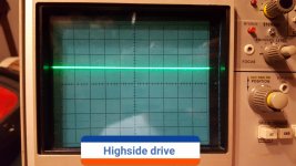
On the highside Probe ground on Source leg and probe on the gate I get a little over 1 volt see picture below.
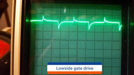
On the lowside Drive if I put the probe ground to -12 volt terminal I get what's shown in the low side pic below.
If I take the low side Drive with the probe ground on the source leg the amp goes in protect as soon as I touched the source leg with the probe ground.
On the lowside Drive if I put the probe ground to -12 volt terminal I get what's shown in the low side pic below.
If I take the low side Drive with the probe ground on the source leg the amp goes in protect as soon as I touched the source leg with the probe ground.
Attachments
Ok so pin 3 of the driver board header is connected to The Collector pin on q21.
I wasn't getting continuity on the meter because it goes through a zener diode d32 and a SMD capacitor c40.
But with the amp powered on I have 3v coming from The Collector On q21 through the zener diode D32 and capacitor C40 directly to Pin 3.
So should I pull q21?
I wasn't getting continuity on the meter because it goes through a zener diode d32 and a SMD capacitor c40.
But with the amp powered on I have 3v coming from The Collector On q21 through the zener diode D32 and capacitor C40 directly to Pin 3.
So should I pull q21?
Last edited:
Okay I pulled q21 and the 3 volts on pin 3 of the driver board header is gone.
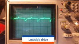
The low side Drive still looks about the same probe ground on -12 volt terminal and Probe on low side Gates.
1v 10us x10
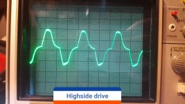
The high side there is a waveform now probe ground on Source pad and probe on high side gate pad.
5v 5ms x10
Pics below of waveforms
The low side Drive still looks about the same probe ground on -12 volt terminal and Probe on low side Gates.
1v 10us x10
The high side there is a waveform now probe ground on Source pad and probe on high side gate pad.
5v 5ms x10
Pics below of waveforms
Attachments
Last edited:
- Status
- This old topic is closed. If you want to reopen this topic, contact a moderator using the "Report Post" button.
- Home
- General Interest
- Car Audio
- Audiopipe AP1500D issue