Good day everyone.
I just opened a CACTUS SOUND ELT.12 amplifier (13.5kw amplifier).
I found the power supply exploded and some output mosfets shorted.
I really believe this is the reason for the failure.
Due to the careless owner, too low impedance or limited supply current, the output section gave way and put the power supply under stress which then exploded.
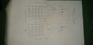
It is an amplifier in full bridge operation because it has 2 separate channels that can be used individually or in bridge, but honestly, those who buy this amplifier will always use it in bridge.
I have a huge problem, the output mosfets are IRFP4242 that are no longer available, only UTSOURCE has them, but they are clearly counterfeit, so I would like to find a valid substitute that will work.
I have not yet repaired the power supply because I am waiting for spare parts, but I can say with precision that the rail capacitors are 200V, but I have doubts if the rail is single or dual.
Being a full bridge with the possibility of using it in STEREO MODE, I think there is a central tap, so I have the idea that the rail is not too far from +/- 140 or 150v (which seems very exaggerated, because the original mosfets support a voltage of 300v, very much at the limit of endurance) but it may be that I'm wrong.
Do any of you have the schematic?
or, does anyone have any idea what can be used instead of IRFP4242?
I just opened a CACTUS SOUND ELT.12 amplifier (13.5kw amplifier).
I found the power supply exploded and some output mosfets shorted.
I really believe this is the reason for the failure.
Due to the careless owner, too low impedance or limited supply current, the output section gave way and put the power supply under stress which then exploded.
It is an amplifier in full bridge operation because it has 2 separate channels that can be used individually or in bridge, but honestly, those who buy this amplifier will always use it in bridge.
I have a huge problem, the output mosfets are IRFP4242 that are no longer available, only UTSOURCE has them, but they are clearly counterfeit, so I would like to find a valid substitute that will work.
I have not yet repaired the power supply because I am waiting for spare parts, but I can say with precision that the rail capacitors are 200V, but I have doubts if the rail is single or dual.
Being a full bridge with the possibility of using it in STEREO MODE, I think there is a central tap, so I have the idea that the rail is not too far from +/- 140 or 150v (which seems very exaggerated, because the original mosfets support a voltage of 300v, very much at the limit of endurance) but it may be that I'm wrong.
Do any of you have the schematic?
or, does anyone have any idea what can be used instead of IRFP4242?
Identical to SS XXX15000D.Photo of main and audio driver board?
He use 2 driverboard with ir2113s configured as stereo or mono.
For more information, on the other chips on the driverboards, this afternoon, as soon as I get back to the lab, I will be able to check thoroughly.
Attachments
Actually I haven't started yet because I'm waiting for spare parts to be able to repair at least the power supply.Are you going to try to do any troubleshooting before you find suitable replacements for the outputs?
As long as the power supply does not start, I cannot verify what the rail voltage is (single or dual).
But I know for sure that I will have to replace almost everything, because the power mosfets have exploded and those of the output section have not exploded but present a short circuit between all their 3 pins.
The courier is about to arrive at its destination, so I think that today in the laboratory I will be able to repair at least the power supply.
But once this is done, I will have serious problems with the audio, because the original mosfets cannot find them.
I had seen some IXYS mosfets, they are excellent, and they are also easy to drive, they are fast, maybe too much, and they support a stratospheric current, but they cost a lot and have a VGS of + -20v, IRFP4242 has a VGS + -30v.
To know if mosfets with VGS + -20v can also work well, I have to turn on the amplifier because I need to know how the IR2113S are powered (12 or 18 or 24v) for example, in the old lanzar opti4000 an IR2113S was used powered at +18 or + 24v and irfp360 were used which had a VGS of + -30v.
As you know I worked on a few Hertz MP15k, which uses the same board. One with blown PS and class d section. Replaced mosfets and drivers in PS etc.
Check also the 4 output relais, I had them with stuck contacts. I used the utsource IRFP4242 they work at least (...) with other mosfets I tried, it did go in protection.
Check also the 4 output relais, I had them with stuck contacts. I used the utsource IRFP4242 they work at least (...) with other mosfets I tried, it did go in protection.
Back on this amplifier, unfortunately the material for repairing the power supply has not yet been delivered.
I was looking at some mosfets in the IXYS catalog.
I noticed the IXFH52N30P that maybe could work:
here are the datasheets of both mosfets:
the original one:
IRFP4242PBF pdf, IRFP4242PBF description, IRFP4242PBF datasheets, IRFP4242PBF view ::: ALLDATASHEET :::
what I would like to use:
https://www.tme.eu/Document/f00df7be960c9ec7c0c999b4dc21a492/IXF(V,H)52N30P(S).pdf
what do you think?
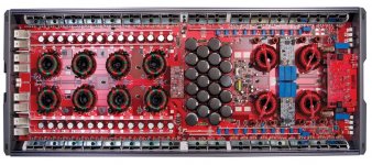
Ok, I repaired the power supply, finally the courier brought my stuff.
I removed the audio mosfets and turned it on;
everything works well, without audio mosfet the rail voltage rises a lot, even to +/- 207 volts (in the long run).
I made sure both drivers were working, and indeed they are.
I reinstalled only a few IRFP4242 mosfets that had survived, I turned on, the amp works perfectly and the rail voltage (with 14.3v power supply) is +/- 156v.
IR2110S are powered at 12v (with reference to -rail) for this reason, mosfets with VGS of +/- 20V can be used.
Correct me if I'm wrong with some guess or test.
The photo show how the amp power supply work
Attachments
Last edited:
If it's working with a partial load of outputs, it's likely OK.
For virtually all amps that have only a single supply rail, the low-side FET source legs read 0 ohms to ground.
It's rare that any of the driver ICs use more than 15v on the low-side supply. 12v is the most common. There's no benefit of going higher and too much switching loss at higher voltage.
For virtually all amps that have only a single supply rail, the low-side FET source legs read 0 ohms to ground.
It's rare that any of the driver ICs use more than 15v on the low-side supply. 12v is the most common. There's no benefit of going higher and too much switching loss at higher voltage.
So do you think that IXFH52N30P can replace IRFP4242 in this application?If it's working with a partial load of outputs, it's likely OK.
For virtually all amps that have only a single supply rail, the low-side FET source legs read 0 ohms to ground.
It's rare that any of the driver ICs use more than 15v on the low-side supply. 12v is the most common. There's no benefit of going higher and too much switching loss at higher voltage.
I'm not sure about the voltage. I don't know where they break down.
Otherwise, they should be OK (looking at the specs). Of course, class D amps are sometimes notoriously finicky about the outputs.
The ixys FETs may be easier to switch/drive 'on' so deadtime may be an issue. It should be easy to adjust with this amp if it is a problem.
Otherwise, they should be OK (looking at the specs). Of course, class D amps are sometimes notoriously finicky about the outputs.
The ixys FETs may be easier to switch/drive 'on' so deadtime may be an issue. It should be easy to adjust with this amp if it is a problem.
Can you explain?I'm not sure about the voltage. I don't know where they break down.
The ixys FETs may be easier to switch/drive 'on' so deadtime may be an issue. It should be easy to adjust with this amp if it is a problem.
Increasing or decreasing the value of the gate or pulldown resistor?
The FET has an intrinsic diode that acts like a Zener diode. The 4242 rates the breakdown of that diode at 360v. That voltage isn't stated for the ixys FET. It's likely OK but if you run into problems, that could be the problem.
I think that the 22 ohm that's in parallel with a diode, near the gate resistors, could be used to adjust the deadtime.
I think that the 22 ohm that's in parallel with a diode, near the gate resistors, could be used to adjust the deadtime.
From what I read in the datasheet of the IXYS, the 52n30p has VDS (avalanche) = VDS, that is, the breakdown voltage is the same as the operating voltage, therefore 300volt, in fact the words "AVALANCHE RATED" are reported but I cannot understand very well.The FET has an intrinsic diode that acts like a Zener diode. The 4242 rates the breakdown of that diode at 360v. That voltage isn't stated for the ixys FET. It's likely OK but if you run into problems, that could be the problem.
I think that the 22 ohm that's in parallel with a diode, near the gate resistors, could be used to adjust the deadtime.
If it is true that VDS is the breakdown voltage of the DS junction and VDS(avalanche) is the breakdown voltage of the body diode, then (since IRFP4242 has a VDS of 300V) why a lower avalanche voltage of the body diode compared to that of the DS junction must be a problem?
If the rail voltage goes to ±200v, you can test the new FETs.
Solder a wire, gate to source.
Connect the source to the negative rail.
Connect the drain to the positive rail VIA A LIMITER. I'd suggest a low wattage 220v (not 12v) incandescent lamp.
Power the amp up and let the voltage creep up. monitor the voltage across the rails AND the voltage across the limiter. When you see the voltage across the limiter start to climb, reading the voltage across the rails will tell you the avalanche voltage.
Watch closely. If the FET isn't clamped tightly to the heatsink, it will heat up quickly.
This is assuming that the voltage across the rails slowly creeps up to 400v.
The rail voltage reaches +/- 200v only if there are no output mosfets.If the rail voltage goes to ±200v, you can test the new FETs.
Solder a wire, gate to source.
Connect the source to the negative rail.
Connect the drain to the positive rail VIA A LIMITER. I'd suggest a low wattage 220v (not 12v) incandescent lamp.
Power the amp up and let the voltage creep up. monitor the voltage across the rails AND the voltage across the limiter. When you see the voltage across the limiter start to climb, reading the voltage across the rails will tell you the avalanche voltage.
Watch closely. If the FET isn't clamped tightly to the heatsink, it will heat up quickly.
This is assuming that the voltage across the rails slowly creeps up to 400v.
By installing only a few mosfets (among those that survived), the rail voltage reaches +/- 156v (14.2v battery voltage) even after a few minutes after switching on, so beyond that voltage it does not go.
The proof you suggested should be made without output mosfets installed?
So with flying leads?
Sorry for this, but ... do you think that given the massive destruction it´s worth trying to repair it?
I´m seeing 64 MosFets per amplifier in that picture, a massive short which cracked half of them and shorted the others must also have blown traces ... plus I don´t think you have a Service manual or at least a schematic.
I worry final repair cost (including your Bench time of course) will exceed replacement price.
Happens to me many times, customer does not want to pay the estimated bill , plus he´s typically impatient, and just replaces it.
- Status
- This old topic is closed. If you want to reopen this topic, contact a moderator using the "Report Post" button.
- Home
- General Interest
- Car Audio
- Cactus Sound ELT.12 - Output Replacement