So i have MTX RT2400X for a repair. PS, output section a lot of diodes dead, a lot of damage but all the traces are good so i'm going to give it a shot.
I've pulled out all of the PS and Output fets, removed even the rectifiers. This amp has been repaired very badly before getting into my hands, so i don't really trust that this are the original parts which are being fitted now.
Gate drive looks great for the PS, so i've decided to put two sacrificial IRFZ44N, one per bank for testing purposes. I get 1.8A of constant current pull from my power supply. Fets get very hot quickly. I've removed them and put a new ones - p60nf06 (these were the ones which were fitted when the amp came in for a repair but I think the original ones are HUF75339 according to another thread in this forum). Same. Tried with irf3205 - same...so it's not the FETs, its not the TL494, not the buffer transistors, because gate drive looks great. Something else is making them hot...
I've checked the center pin of the positive rectifier. Without the remote in - 0v. The other two pins are sitting at 12v. When I apply the remote, center pin gets 12v slowly rising from 0.
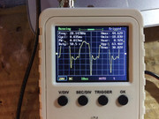
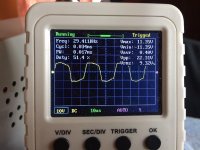
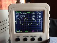
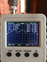
But the wave at the other two pins looks awful (this is without the rectifiers in). I wil attach pictures.
If I fit the rectifiers back - same - 1.8A of current pull and fets get hot quickly. I'm pretty sure 2A of current at idle is way to much for this amp. Maybe it does need all of the 6 FETS in place in the PS ?!
I've pulled out all of the PS and Output fets, removed even the rectifiers. This amp has been repaired very badly before getting into my hands, so i don't really trust that this are the original parts which are being fitted now.
Gate drive looks great for the PS, so i've decided to put two sacrificial IRFZ44N, one per bank for testing purposes. I get 1.8A of constant current pull from my power supply. Fets get very hot quickly. I've removed them and put a new ones - p60nf06 (these were the ones which were fitted when the amp came in for a repair but I think the original ones are HUF75339 according to another thread in this forum). Same. Tried with irf3205 - same...so it's not the FETs, its not the TL494, not the buffer transistors, because gate drive looks great. Something else is making them hot...
I've checked the center pin of the positive rectifier. Without the remote in - 0v. The other two pins are sitting at 12v. When I apply the remote, center pin gets 12v slowly rising from 0.
But the wave at the other two pins looks awful (this is without the rectifiers in). I wil attach pictures.
If I fit the rectifiers back - same - 1.8A of current pull and fets get hot quickly. I'm pretty sure 2A of current at idle is way to much for this amp. Maybe it does need all of the 6 FETS in place in the PS ?!
Last edited:
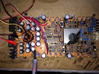
Refitted the rectifiers and all of the new 6 PS Fets - p60nf06.
So I do have rail voltages of +49.5vrms and -50.3vrms, but the power supply mosfets are getting pretty hot after 10seconds, even that the gate drive looks kind-a OK.
2A of current pull at idle...doesn't seem alright to me. LED is staying RED.
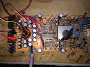
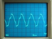
Here are pictures of the board (before putting all of the PS Fets and rectifiers) and how does the wave looks at the gate and source of the Power Supply Mosfets...What I noticed is that on the TL494 and the buffer transistors the same gate drive looks awful, but once it passes the small choke near the transformer, it gets the way it is on the pads of the PS Mosfets (pictures attached).
What I'm concern is primarily the amount of heat the power mosfets are generating...I've repaired at least 100+ amplifiers so far and none of their Power Supply section was getting even warm when working correctly.


So I do have rail voltages of +49.5vrms and -50.3vrms, but the power supply mosfets are getting pretty hot after 10seconds, even that the gate drive looks kind-a OK.
2A of current pull at idle...doesn't seem alright to me. LED is staying RED.
Here are pictures of the board (before putting all of the PS Fets and rectifiers) and how does the wave looks at the gate and source of the Power Supply Mosfets...What I noticed is that on the TL494 and the buffer transistors the same gate drive looks awful, but once it passes the small choke near the transformer, it gets the way it is on the pads of the PS Mosfets (pictures attached).
What I'm concern is primarily the amount of heat the power mosfets are generating...I've repaired at least 100+ amplifiers so far and none of their Power Supply section was getting even warm when working correctly.
Last edited:
An externally hosted image should be here but it was not working when we last tested it.
An externally hosted image should be here but it was not working when we last tested it.
An externally hosted image should be here but it was not working when we last tested it.
Why are you posting such small images?
I've had one model of MTX amp that the FETs ran hot no matter what. I don't know if that's normal for this model and didn't notice it on the 2300.
Is the bias set too high?
Are the two gate resistors within tolerance?
The attached is the gate drive from an MTX 2300 (I think).
I've had one model of MTX amp that the FETs ran hot no matter what. I don't know if that's normal for this model and didn't notice it on the 2300.
Is the bias set too high?
Are the two gate resistors within tolerance?
The attached is the gate drive from an MTX 2300 (I think).
Attachments
I uploaded the photos to two different free web servers, but every time I try to insert the link for the actual address (url) of the photo, the forum php engine makes them into thumbnail image instead of pasting the original source link (url) into them...never had this issue before and I browse like 30+ forums a week.
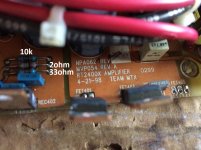
Bias knob doesn't seems to affect this. Gate resistors are only 2 pieces - 1 per bank ~ 33ohms and they are rated 1W or 2W, not the smaller ones with the lower power rating...They read exactly 33ohms.
And I see no current changes ,no matter rectifiers out, or rectifiers in. Still pulling out 1.8-2.0A at idle. Nothing else is heating up, except the power supply fets.
The weird wave is the gate drive directly measured on the TL494 pin 8 and 11.
Attachments
Last edited:
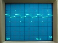
Thank You Perry for the reference. So gate drive at tl494 is almost the same as yours.
The amplifiers are similar, they are from the same line and same era and even the boards look really close.
Gate resistors are original as there is no any sign of soldering/desoldering, so no doubt in this. But i'm starting to wonder if the p60nf06 are the original PS mosfets, if they are not, maybe that's why they are getting hot as they don't match the design. As I mentioned earlier, it had some other repairs before me, so maybe the other guy had fitted wrong fets ?!
3205's are getting even hotter for a even shorter period of time than p60nf06...
I checked every diode and transistor in the power supply section and all reads fine...as I saw in another thread over the forum here, the original PS fets are supposed to be HUF75339 ...i will try to find some of these and see if this will change anything...
Thanks for the input Perry !
I use 3205s in the 2300s.
Have you tried reducing the gate resistor value?
What's the date on the board? The amp that made the FETs heat up was made in 8/27/98. There was nothing that could be done to make those run cool. I tried everything that I could think of since I had multiple amps of the same model to repair. Even with the heating FETs, they were reliable.
The driver transistors were fine, hfe > 250.
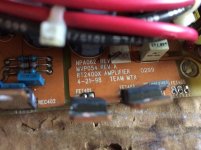
All the resistors are within tolerance and correspond to their marking.
There is no 1k resistor in this group or the one at the other side of the board...And I can say within 99% that these were fitted from the factory as I can see that there were no soldering in this area.
And yes the gate resistor is bottom one. This is the one i've changed, but due to making it worse, i've soldered the old one back.
Attachments
Last edited:
Checked that 1k resistor out of the board - reads fine, it is in tolerance...
No, there is no carbonized area or blackened - none. I know it can become conductive.
There are also at least 5 diodes - 1N4150 which are shorted in the amplifier section, some of the Mosfets -IRF540N are gone and maybe some driver/buffer transistors mpsa** which i still have to check...
When everything gets here, I will post an update.
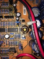
The glass diodes - 1N4150 surely are the original parts (no signs of soldering). That's what is written on them. 2 of them even shattered in my hands when i was trying gently to pull them off from the board.
Actually some of the amplifier mosfets are IRF540N, some of them IRF540 - there are even like 3 or 4 different manufacturers. It's obvious that there were some incompetent attempts for repair...i'm glad at least they didn't damage the board or the pads...
And I don't have any schematics so i don't know what was exactly fitted from the factory...Perry can You tell what was the 2300 model using ?!
- Status
- This old topic is closed. If you want to reopen this topic, contact a moderator using the "Report Post" button.
- Home
- General Interest
- Car Audio
- MTX RT2400X repair issues