The high frequency 80k hertz
Is that signal on either of the outputs of the LM219 on the driver board, right now?
I tried the MMBTA06/56 and the amp wasn't happy. I had to use the originals.
One of these board may have the 4401/3s in the power supply. Something like the A06/56 will work in the power supply so you could swap them to get the drivers if you don't want to wait on ordering them.
One of these board may have the 4401/3s in the power supply. Something like the A06/56 will work in the power supply so you could swap them to get the drivers if you don't want to wait on ordering them.
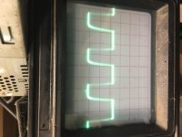
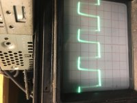
After replacing the divers with original part numbers and the 2 optocouplers on 1 board this is the drive signals I get in the high and low side outputs
Do these drive signals appear good or do I have a problem somewhere still ?
Scope settings are 5us 5volts/div
Do these drive signals appear good or do I have a problem somewhere still ?
Scope settings are 5us 5volts/div
Attachments
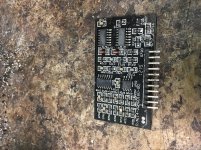
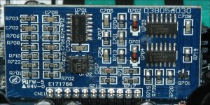
Here is a picture of the audio driverboard .
Do you know what ic controls the drive signal for the outputs ?
There is something defective on the driverboard which is causing 1 board to have no drive signal to the outputs .
I swapped audio driverboard a and the amp has drive signal on the outputs but this audioboard makes the amp have no drive signal
Attachments
All of the components have to pass their respective signals. Start by posting the voltage on the header. A marginal voltage there may let one board work where the other won't.
Before pulling the working board, make a note of all pins of all ICs that have the 80kHz square or triangle waveform (no audio input).
Before pulling the working board, make a note of all pins of all ICs that have the 80kHz square or triangle waveform (no audio input).
Voltage on the header of both boards
Non working board
Pin 1:-4.61
Pin 2:0.00
Pin 3:0.00
Pin 4:-12.97
Pin 5:12.97
Pin 6:0.11
Pin 7:5.00
Pin 8:0.00
Pin 9:5.00
Pin 10:0.21
Pin 11:4.66
Working board
Pin 1:0.00
Pin 2:0.00
Pin 3:0.00
Pin 4:-13.10
Pin 5:12.86
Pin 6:0.11
Pin 7:0.11
Pin 8:0.00
Pin 9:4.99
Pin 10:0.21
Pin 11:0.19
Non working board
Pin 1:-4.61
Pin 2:0.00
Pin 3:0.00
Pin 4:-12.97
Pin 5:12.97
Pin 6:0.11
Pin 7:5.00
Pin 8:0.00
Pin 9:5.00
Pin 10:0.21
Pin 11:4.66
Working board
Pin 1:0.00
Pin 2:0.00
Pin 3:0.00
Pin 4:-13.10
Pin 5:12.86
Pin 6:0.11
Pin 7:0.11
Pin 8:0.00
Pin 9:4.99
Pin 10:0.21
Pin 11:0.19
I’m working on this amp again replacing the lm219.
I noticed that neither board has drive signal on the outputs again .
I ordered new optocouplers .
1 set of optocouplers says
Lite-on high speed optocoupler 10MBd
The other set says
10Mbd open collector high speed optocoupler.
Are these the same pretty much or wondering what one I should use in this amp
- Status
- This old topic is closed. If you want to reopen this topic, contact a moderator using the "Report Post" button.
- Home
- General Interest
- Car Audio
- Audiopipe AP 3000 1D