Goodmorning everyone. I've just finished repairing this amp.
It worked very well at 12.6 volts, but as soon as I raised the voltage to 14.4 - 14.6 volts, 2 stages of IRS21844 were burned and the related output mosfets were also brought along.
I then replaced again thinking of a defect, but now, I do not detect any waveform on the low side gate of the mosfet (keep in mind that while I'm doing this test, there are no mosfets installed, only the driver board).
The amplifier turns on and does not go into protection but it seems muted because on the low side there is not the waveform that I would expect with a 50hz signal at the input.
All regulators work and produce the right voltages and on the driver board input (when the driver board is not mounted) there is a perfect sine wave of the frequency I am using at the input, while with the mounted driver board, the signal audio at its input is cut sharply on the negative half-wave, for this reason I thought of a faulty tl072, so I replaced everything (tl072 - lm211 - all SMD transistors and all irs21844s) but the problem remains.
What do you advise me to watch?
can i solder this directly to C6?Solder a 10k resistor between legs 1 and 2 of the TL072.
Does that change anything?
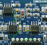
DWM3640NHVC6 will work on some driver boards but I don't know which one you have.
Hi Perry, I tried what you told me, but the result does not change.Solder a 10k resistor between legs 1 and 2 of the TL072.
Does that change anything?
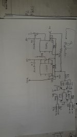
In fact, I did some investigations and I did a reverse engineering job.
This is the oscillator scheme (excluding LM293 for protection and IRS21844 as final driving stage).
I noticed that at the out of LM211 I have a perfect square wave (with signal 50 hz strong in input) as I would expect, this perfect wave continuous up to the bases of 3904 and 3906 (immediately after the out of LM211) .
This same wave continues up to the 2D emitters near the IRS21844 but the signal disappears at their collectors.
Please note that at the time I am performing these tests, all IRS21844 are off the board.
I noticed that the bases of the 2D are placed at GND, so I can not understand how it is possible that the signal is interrupted at that point. All transistors, 3904, 3906, MMBTA92, MMBTA42 and MAX have been tested and operating correctly and all GND tracks have been tested and existing without any interruptions.
Attachments
Are the rectifiers in the circuit?
Yes
Unfortunately at the moment I'm not in the laboratory, but I think one thing:What's the DC voltage on pin 1 of U6?
The protection circuit managed by LM293 acts only on muting transistors (MAX) that send the SD pin of the IRS to negative rail if there is a problem or when the amplifier is turned on in order to stop the drivers temporarily or permanently (protection ).
If we assume that there is an anomaly in the protection circuit and that the oscillator is still working (in fact, in my case, the oscillator works up to the 2D transistors, then stops) for which reason LM293 could affect the operation of the oscillator section , considering the fact that up to the 2D TRANSISTOR the signal is present, after disappears, that the IRS pin 1 is not affected by anything of protection by LM293 and that the IRS are currently out of the circuit?
I find it very strange, I know that the IRS pin 1 ALWAYS receives the signal from the 2D transistors (in cases where the amplifier is not in protection).Pin 1 is pulled to the negative rail by the two MAX transistors. Those transistors are driven by pin 6 of the 293.
The one who is being negative-railed is actually IRS pin 2, not pin 1.
But in this case, all the IRSs have been removed and so even if pad 2 of IRS were put in a negative track, pad 1 (coming from 2D) should still receive signal.
Look at the schematic.
Attachments
You're right. The MAX transistors pull pin 2 down.
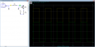
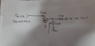
Do you see a square wave of ±5v going into the 820 ohm resistor but only swinging 0.7v positive and 5v negative on the other side of the 820 ohm resistor?
yes Sir., a perfect ±5v squarewave after and before the 820ohm resistor ( no 0.7 positive and 5v negative on the other side of the resistor) but anything on 2Ds collector, so anything to IRS pin1.
very strange but true.How can the voltage go more than 0.7v above ground since the Vbe diode would be conducting after about 0.6v?
See attached.
I thought the 2.4k resistor is open or damaged, look at the schematic. It could be possible?
Attachments
- Status
- This old topic is closed. If you want to reopen this topic, contact a moderator using the "Report Post" button.
- Home
- General Interest
- Car Audio
- Emphaser EA15000SPL problem