Here is what the voltages are now:
Opto:
Pin 1: +1.15
Pin 2: 0.00
Pin 3: 0.00
Pin 4: +12.1
Pin 5: + 12.3
Pin 6: +12.7
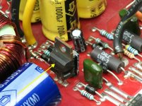
Small transistor (MPSA06 behind opto):
leg 1: +12.3
leg 2: +12.1
leg 3: +11.48
Thermostat:
+ 11.48 on both
494:
Pin 1: +1.9
Pin 2: +1.9
Pin 3: +1.9
Pin 4: +7.0
Pin 5: +1.48
Pin 6: +3.4
Pin 7: -0.00
Pin 8: +11.49
Pin 9: -0.00
Pin 10: -0.00
Pin 11: +11.49
Pin 12: +11.49
Pin 13: +4.92
Pin 14: +4.93
Pin 15: +2.2
Pin 16: -0.00
Opto:
Pin 1: +1.15
Pin 2: 0.00
Pin 3: 0.00
Pin 4: +12.1
Pin 5: + 12.3
Pin 6: +12.7
Small transistor (MPSA06 behind opto):
leg 1: +12.3
leg 2: +12.1
leg 3: +11.48
Thermostat:
+ 11.48 on both
494:
Pin 1: +1.9
Pin 2: +1.9
Pin 3: +1.9
Pin 4: +7.0
Pin 5: +1.48
Pin 6: +3.4
Pin 7: -0.00
Pin 8: +11.49
Pin 9: -0.00
Pin 10: -0.00
Pin 11: +11.49
Pin 12: +11.49
Pin 13: +4.92
Pin 14: +4.93
Pin 15: +2.2
Pin 16: -0.00
From this point, on, if you have 12v on both sides of the thermostat, the voltages on that opto and transistor are OK. You can check them but you don't need to post them.
Pin 4 shouldn't be high. Connect it to pin 7 with a short jumper wire. There could be a bad component so power it up for a few seconds at a time to see if anything in the area gets hot. Also monitor the rail across the rectifiers.
The various, normally heatsink mounted components may get hot as the amp is now.
Just power it up to see if you can get rail voltage.
Connect a jumper wire between pins 4 and 7 on the 494. Pin 4 is high. This will ground it. There are many ground points but pin 4 is sensitive and needs to be connected to pin 7 as the ground point.
The voltage on pins 1-3 also may indicate that there is some leaked electrolyte. I don't, however, understand why it's so different from the first readings.
The voltage on pins 1-3 also may indicate that there is some leaked electrolyte. I don't, however, understand why it's so different from the first readings.
- Status
- This old topic is closed. If you want to reopen this topic, contact a moderator using the "Report Post" button.
- Home
- General Interest
- Car Audio
- Once again need help fixing Orion HCCA 225 Digital Reference