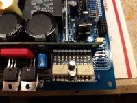
Hey folks, I've got this Audison I'm working on and as far as I can tell the class d driver circuitry is a fairly novel design. It appears that the triangle wave is generated by a 555 timer which is then fed to a high speed comparator. After that it gets fairly odd, I haven't studied it very in depth yet, but it appears that the outputs are driven by high speed optocouplers, and not driver transistors like most amps.
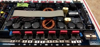
I'd love to get a service manual for it, I'd be happy to pay for it. I'm trying to get an idea of what it's going to cost to repair it. It only blew a few power supply fets, but with changing all parallel parts and compliments it's going to mean full rebuild of the supply. I got the supply running with minimal parts and moved on to the power amp. It had one shorted fet in the power amp, I swapped it just to do testing on this class d driver circuit, but the amp will not power up with the output daughter cards installed. It flashes a code on its status LEDs, but the manual doesn't detail what it means, just that it requires service.
I'm mostly wondering if anyone has come across this class d design before, and if you might have any pointers.
Attachments
AUDISON LRX 1.400 SM Service Manual download, schematics, eeprom, repair info for electronics experts
Maybe this helps... Audison is very complicated to my opinion, but in this Forum are some specialist for that amp.
Maybe this helps... Audison is very complicated to my opinion, but in this Forum are some specialist for that amp.
Hello,
Nonvtec1992:
R12 is a 1K resistor while R3 is 680 Ohm
jacampb2:
this amp is difficult to repair, if you still want to proceed I can try to give you my support.
The whole scheme is complex because it is composed only of blocks and modules connected by many networks and is almost useless.
In the meantime, it would be useful to know which components have been replaced in detail, what are the conditions in which the amplifier is switched on and which LEDs light up.
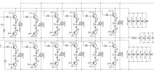
Schematic of one of the two amplifier modules is attached.
If you've found a shorted fet, check / change components that are connected to it.
Note that each amp module is a card so you can easily remove it like any other daughter card.
My advice is to check ALL components on the module, fet, resistors and transistor, one by one.
Nonvtec1992:
R12 is a 1K resistor while R3 is 680 Ohm
jacampb2:
this amp is difficult to repair, if you still want to proceed I can try to give you my support.
The whole scheme is complex because it is composed only of blocks and modules connected by many networks and is almost useless.
In the meantime, it would be useful to know which components have been replaced in detail, what are the conditions in which the amplifier is switched on and which LEDs light up.
Schematic of one of the two amplifier modules is attached.
If you've found a shorted fet, check / change components that are connected to it.
Note that each amp module is a card so you can easily remove it like any other daughter card.
My advice is to check ALL components on the module, fet, resistors and transistor, one by one.
Attachments
Hello,
Nonvtec1992:
R12 is a 1K resistor while R3 is 680 Ohm
jacampb2:
this amp is difficult to repair, if you still want to proceed I can try to give you my support.
The whole scheme is complex because it is composed only of blocks and modules connected by many networks and is almost useless.
In the meantime, it would be useful to know which components have been replaced in detail, what are the conditions in which the amplifier is switched on and which LEDs light up.
Schematic of one of the two amplifier modules is attached.
If you've found a shorted fet, check / change components that are connected to it.
Note that each amp module is a card so you can easily remove it like any other daughter card.
My advice is to check ALL components on the module, fet, resistors and transistor, one by one.
Thanks, I appreciate the input but I've gotten the amp running.
Thanks,
Jason
hey ppalli im repairing lrx 1.2k i it´s long repair for about 5yrsHello,
Nonvtec1992:
R12 is a 1K resistor while R3 is 680 Ohm
jacampb2:
this amp is difficult to repair, if you still want to proceed I can try to give you my support.
The whole scheme is complex because it is composed only of blocks and modules connected by many networks and is almost useless.
In the meantime, it would be useful to know which components have been replaced in detail, what are the conditions in which the amplifier is switched on and which LEDs light up.
Schematic of one of the two amplifier modules is attached.
If you've found a shorted fet, check / change components that are connected to it.
Note that each amp module is a card so you can easily remove it like any other daughter card.
My advice is to check ALL components on the module, fet, resistors and transistor, one by one.
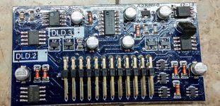
 and i get on it today, power section was blown so i repair it and nowi spot one sot-23 trans or somethink like that on DLD.1 card marking on smd is GK or 6K GK is BD48L39G and 6K is TP0610K can you please help with driver schematic output wasnt blown
Sot23 is CMPE4392, signal jfet, and it is difficult to measure
You have to know the way to measure it right, it's different from measuring a bjt. often seems shortcircuit but it's ok.
This jfet is to limit the signal when you have an output current overload, so to see if everythink works, you can remove it,
DLD.1 schematic coming soon.....
You have to know the way to measure it right, it's different from measuring a bjt. often seems shortcircuit but it's ok.
This jfet is to limit the signal when you have an output current overload, so to see if everythink works, you can remove it,
DLD.1 schematic coming soon.....
i desolder it and it happend again so i keep it desoldered and after i remove output mosfet cards on both sides it starts run and current at idle is 1.7 -1.8 Amp at 11.7v when output cards are in it relays click and it resart to protect output cards seems that are not shorted
- Home
- General Interest
- Car Audio
- Audison LRx 1.2k repair