Hello, i have this amplifier and it randomly goes into protection mode.
Sometimes it turns on fine, all 4 channels have good output signal but after that if i turn it off and turn on it would turn with protection and won't turn on.
Could this be psu pwm chip? It uses TL494. There is +28v and -28v when it works normally (with 12v input) but not when it's in protection, no drive signals on psu mosfets.
Attachments
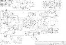
Measure DC voltages around the TL494 both in and out of protection.
There may be an issue with the soft start circuit not supplying enough voltage to latch the TL494 and after turn off the the circuit does not drain off enough voltage to allow the soft start capacitor to charge up enough after recycling the amp.
There may be an issue with the soft start circuit not supplying enough voltage to latch the TL494 and after turn off the the circuit does not drain off enough voltage to allow the soft start capacitor to charge up enough after recycling the amp.
First number is when it's turned on, second one in protection (14.5V input voltage, negative probe was on ground)
Pin 1 - 1,8V 1,9V
Pin 2 - 3,86V 0,5V
Pin 3 - 100mV 4,53V
Pin 4 - 200mV 100mV
Pin 5 - 1,42V 1,45V
Pin 6 - 3,71V 3,9V
Pin 7 - 0V 0V (GND)
Pin 8 - 13,9V 14,5V
Pin 9 - 5,15V 0V
Pin 10 - 5,15V 0V
Pin 11 - 13,9V 14,5V
Pin 12 - 13,9V 14,5V
Pin 13 - 5V 5V
Pin 14 - 5V 5V
Pin 15 - 13,9V 14,5V
Pin 16 - 12V 12V
Whatever is causing Pin 2 of the 494 to go low and Pin 3 to go high is disabling the output drive pins 9 & 10. So, you will not have the +/- Rails.
Because you have good output with no DC offset when the amp is not in protection, leads me to believe the problem is in the protection circuit itself.
There should be a way to disable the protection circuit. Try lifting D4 and cycle through turn on and turn off a few times. If the amp does not go into protection, something on the other side of D4 may be causing the intermittent, such as cold solder joint,broken lead, weak device or leaky cap. If not try D20 and follow the same procedure.
There is always a risk when disabling protection, use the usual precautions.
I couldn't upload that same pdf 
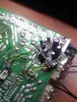
Anyway, i desoldered smd transistors, tested them and resoldered back, it seems to be working fine now. I have different revision of amplifier than in pdf, can't take more pictures of TL494 since i've soldered board back in.
Is there a way to test protection circuit? Like maybe biasing one output transistor too much?
Attachments
Assuming you replaced D4 or anything else you may have removed, clamped board in chassis, and load each amp with a 2 ohm dummy load if you have one, or 2 ohm test speakers or 4 ohm bridged will do.Apply signal with no more than 10 watts power. Use a 12 gauge or bigger short length of cable. Briefly short across each channel. The amp should go into protection and back out again.Short each channel to power ground. You should have the same result.
You can thermal test the amp also. Run amp at or near clipping. Use a 1khz test tone into 2 ohm stereo or 4 ohm bridged dummy load. If running speakers in either configuration, use hard hitting music at high volumes. A test tone is libel to damage the voice coils. Dummy loads will thermal in a shorter time. You may want to let the amp thermal cycle a couple of times.
You can thermal test the amp also. Run amp at or near clipping. Use a 1khz test tone into 2 ohm stereo or 4 ohm bridged dummy load. If running speakers in either configuration, use hard hitting music at high volumes. A test tone is libel to damage the voice coils. Dummy loads will thermal in a shorter time. You may want to let the amp thermal cycle a couple of times.
- Status
- This old topic is closed. If you want to reopen this topic, contact a moderator using the "Report Post" button.
- Home
- General Interest
- Car Audio
- Infinity Reference 475a