Try this...
Signal source >1> cap >2> 1k resistor >3> 10k resistor >> shield of signal source.
Post the AC voltage on points 1, 2 and 3 with the scope ground connected to shield of the signal source. Do this with no connection to the amp. Set the signal source to full volume. Try it at around 20kHz.
Signal source >1> cap >2> 1k resistor >3> 10k resistor >> shield of signal source.
Post the AC voltage on points 1, 2 and 3 with the scope ground connected to shield of the signal source. Do this with no connection to the amp. Set the signal source to full volume. Try it at around 20kHz.
I measured the ipod output using the 1khz tone first since it was consistent and stable. My scope does not have AC coupling so I used my voltmeter, black probe connected to RCA shield ground.
Ipod - capacitor 1.076v
Capacitor - 1k resistor 1.058v
1k resistor to 10k resistor 0.958v
10k resistor to shield ground 0.00
Ipod - capacitor 1.076v
Capacitor - 1k resistor 1.058v
1k resistor to 10k resistor 0.958v
10k resistor to shield ground 0.00
The ipod playing the sweep track. The ac voltage is half that of the other track playing 1khz. The high and low frequencies act differently. 1st reading is 20-200hz approximately, the second is close to 20khz.
Ipod - capacitor 0.55v
Capacitor - 1k resistor 0.52v
1k resistor to 10k resistor 0.
10k resistor to shield ground 0.00
Ipod - capacitor 0.55v
Capacitor - 1k resistor 0.52v
1k resistor to 10k resistor 0.
10k resistor to shield ground 0.00
Performed the test with the voltmeter and the scope.
Results : Voltmeter
Ipod to 0.1uf cpacitor 1.068v
0.1uf cap to 1k resistor 0.534v
1k resistor to RCA shield 0.0
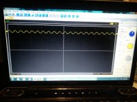
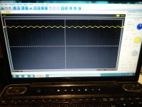
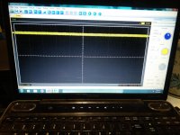
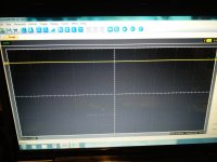
The scope screen shots are at 2.000ms / 5.00v
1khz signal
Pic1 is Ipod to 0.1uf cap
Pic2 is 0.1uf cap to 1k resistor
Pic3 is 1k resistor to RCA shield
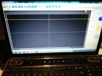
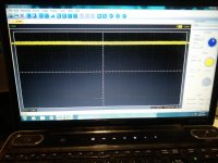
20khz signal
Pic4 is Ipod to 0.1uf cap
Pic5 is 0.1uf cap to 1k resistor
Pic6 is 1k resistor to RCA shield
Results : Voltmeter
Ipod to 0.1uf cpacitor 1.068v
0.1uf cap to 1k resistor 0.534v
1k resistor to RCA shield 0.0
The scope screen shots are at 2.000ms / 5.00v
1khz signal
Pic1 is Ipod to 0.1uf cap
Pic2 is 0.1uf cap to 1k resistor
Pic3 is 1k resistor to RCA shield
20khz signal
Pic4 is Ipod to 0.1uf cap
Pic5 is 0.1uf cap to 1k resistor
Pic6 is 1k resistor to RCA shield
Attachments
I even connected a preamp to the signal to increase the line drive voltage. The signal is still not able to get through.
What could possibly be causing the signal to be drowned out when connected to the collectors of Q9701 and Q9702?
Could it have anything to do with the muting circuit, the- 42v on Q4404, the 5.02v on Q4402 and Q4403? I think that 5.02v is on the emitter of Q9701 and Q9702 also as well as tying into IC9701.
Back to this amp/thread. I am inputting a 100hz sine wave from a Pioneer deck to the RCA inputs of the amplifier.
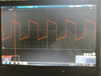
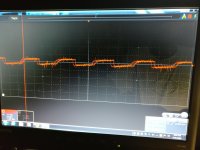
I currently have Q4501 with the emitter jumped to the collector to send 5v towards the base of IC9701/9702. With the scope I am able to see some of the square wave pass through from Q9701/9702 base to collector. This minimized square wave is present on Pin1 of IC9702/9704 and it somewhat decreases and increases when the signal volume is lowered and raised. I can also see the output from Pins 10 and 12 of IC9702/9704 and also at Pins 1/2 and 9/10 of IC9703, but not seeing a good, visible output from Pins 3/4 or 11/12 of IC9703.
Settings: 2v / 5ms div
Pin1 of IC9702
Pin 12 of IC9702
Attachments
- Status
- This old topic is closed. If you want to reopen this topic, contact a moderator using the "Report Post" button.
- Home
- General Interest
- Car Audio
- Alpine MRP-M1000 with rail voltage but no output