Repairing an Alpine MRP-M1000 amp. Replaced Q4901 and the zener diode (ZD4901), also replaced the output ICs (IC9801 and IC9802). I get +/-45v of rail voltage but have no audio output, and no gate drive for the audio outputs. I read all of the MRP-M1000 posts on the forum and have listed some readings that were asked for. It was stated to compare the amp readings with those listed in the service manual so I am listing some that are drastically different.
Leg1 of Q4901 is 11.61v above the negative rail
Leg 2 is at ground
Leg 3 is 12.14 above the negative rail
On the IR2010S ICs I get 11.6v with black probe on Pin15 and red probe on Pin3.
I have audio on pins 1 and 7 of IC1801.
Pin1 of IC4501 is missing 5v.
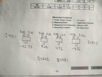
IC4501 IC4502
1) 0.0 5.06
2) 5.05 5.00
3) 0.0 0.0
4) 5.01 0.0
5) 5.05 5.05
IC9801 IC9802
1) - 45.50 - 45.50
2) - 45.50 - 45.50
3) - 33.90 - 33.90
4) 0.0 0.0
5) 0.0 0.0
6) 0.02 0.02
7) 0.01 0.01
8) 0.00 0.00
9) 0.00 0.00
10) 0.00 0.00
11) - 33.91 - 33.91
12) - 45.51 - 45.51
13) - 45.47 - 45.47
14) - 45.51 - 45.51
15) - 45.51 - 45.51
16) 0.00 0.00
E B C
Q9701 - 4.93 - 45.59 - 4.46
Q9702 - 4.92 - 45.59 - 4.46
Leg1 of Q4901 is 11.61v above the negative rail
Leg 2 is at ground
Leg 3 is 12.14 above the negative rail
On the IR2010S ICs I get 11.6v with black probe on Pin15 and red probe on Pin3.
I have audio on pins 1 and 7 of IC1801.
Pin1 of IC4501 is missing 5v.
IC4501 IC4502
1) 0.0 5.06
2) 5.05 5.00
3) 0.0 0.0
4) 5.01 0.0
5) 5.05 5.05
IC9801 IC9802
1) - 45.50 - 45.50
2) - 45.50 - 45.50
3) - 33.90 - 33.90
4) 0.0 0.0
5) 0.0 0.0
6) 0.02 0.02
7) 0.01 0.01
8) 0.00 0.00
9) 0.00 0.00
10) 0.00 0.00
11) - 33.91 - 33.91
12) - 45.51 - 45.51
13) - 45.47 - 45.47
14) - 45.51 - 45.51
15) - 45.51 - 45.51
16) 0.00 0.00
E B C
Q9701 - 4.93 - 45.59 - 4.46
Q9702 - 4.92 - 45.59 - 4.46
Is there something wrong with the Q4901 voltages I posted? Unless I got the pin configuration wrong but I posted those just to indicate that the power supply and rail voltage/regulators are functioning properly. I am assuming my problem is further into the output section, but I may be wrong. I am just supplying answers to questions that were asked in other posts and confirming voltages that you posted when you tested one of these...
When applying signal to the collectors of Q9701 and Q9702, where do I connect the rca ground? Unsure of exactly how to inject the audio...
I connected the rca signal(center pin) to a 0.1uf capacitor and connected the rca signal ground to the rca ground connector. I saw no audio on the output ICs. The only audio I could see was going backwards to IC9701 and beyond to the rca connector, There is no audio in the amp with the rca ground unconnected.
I connected the rca signal(center pin) to a 0.1uf capacitor and connected the rca signal ground to the rca ground connector. I saw no audio on the output ICs. The only audio I could see was going backwards to IC9701 and beyond to the rca connector, There is no audio in the amp with the rca ground unconnected.
The signal doesn't have to be audio but audio may work.
The secondary ground would be what I'd use for ground. If you're using audio (not a square wave generator), I'd insert a 1k-10k resistor in series with it to protect the preamp output.
When you inject the signal, confirm that the signal is present at the point where it's being injected and then check various points in the circuit. You can check at the input to the driver ICs to save some time in case all of the circuit is OK.
I'd think a 5v amplitude signal would be good but I don't know for certain. I've never had to do this with this amp.
Currently monitoring the audio signal with a voltmeter set on AC. Have a USB scope which is not set up at the moment but I can fire it up if absolutely necessary...
I can see the audio signal fluctuations on the rca side of the 0.1uf capacitor but nothing on the Q9701/2collector side of the 0.1uf capacitor. On AC, there is a reading of 0.240v on the Q9701/9702 collectors, Pin1 of IC9702/9704, and Pin12/Pin14 of IC9801/9802.
Don't know if it means anything when reading using AC but Pins 1,2,3,11,12,13,14,15 on the driver ICs all read the same voltage of 0.240v.
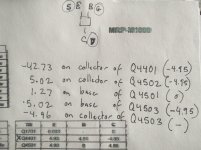
Some more off readings from Q4401, Q4501, Q4502, Q4503.
-42.73 on collector of Q4401 (s.m. says -4.95)
5.02 on collector of Q4502 (s.m. says - 4.95)
1.27 on base of Q4501 (s.m. says 0)
5.02 on base of Q4503 (s.m says - 4.95)
-4.95 on collector of Q4503 (s.m. says -)
-42.73 on collector of Q4401 (s.m. says -4.95)
5.02 on collector of Q4502 (s.m. says - 4.95)
1.27 on base of Q4501 (s.m. says 0)
5.02 on base of Q4503 (s.m says - 4.95)
-4.95 on collector of Q4503 (s.m. says -)
Attachments
#16:
Yes
#14:
If you're using ground as a reference and the rail cap is connected between ground and the negative rail, that capacitance should prevent seeing any ripple or noise.
#15:
The mute/clamp circuit is enabled and Q4503 is driving Q9701/2 on but I think your drive signal should be able to drive through that clamp since the resistors in that circuit are 10k ohms.
So the mute circuit is currently engaged? Is that due to an existing problem or just because there is no signal/input? So none of those voltage readings are indicative of a problem?
What do I do next since introducing a signal at the collectors of Q9701 and Q9702 did not work?
What do I do next since introducing a signal at the collectors of Q9701 and Q9702 did not work?
I will try with the scope. Just to clarify:
I am connecting the signal ground to the secondary ground through a 1k resistor, and the signal through a 0.1uf capacitor to the collectors of Q9701 and Q9702?
And I can use audio for this test?
Can I expect to get audio output at the speaker terminal?
I am connecting the signal ground to the secondary ground through a 1k resistor, and the signal through a 0.1uf capacitor to the collectors of Q9701 and Q9702?
And I can use audio for this test?
Can I expect to get audio output at the speaker terminal?
- Status
- This old topic is closed. If you want to reopen this topic, contact a moderator using the "Report Post" button.
- Home
- General Interest
- Car Audio
- Alpine MRP-M1000 with rail voltage but no output