I'm not referring to your lab power supply, but the amp power supply.the resistances lowered their value, between 5 and 8 kohm
I think that your pulldown rails resistors are fine. Some multimeter have the defect that not read precisely (due to probe's cables resistance and low quality electronics).
But if you want, change the pulldown resistor with same values. It become to smoke another time.
To solve the problem, repair the amp (output stage and driver board) then, install new output mosfet (you do not need to install all at once, to do a test you can also install only 1 for high side and 1 for low side of each stage).
When you have finished repairing, with the proper precautions you can turn on the amplifier and you will notice that those resistors will no longer smoke because the rail voltages will not rise higher than necessary.
Answer to post #11?
forget to show it
Attachments
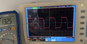
The scope doesn't tell me what I need to know. Does the rail-rail start as soon as rail voltage is produced or is there a short delay?
Excuse me, but I do not understand
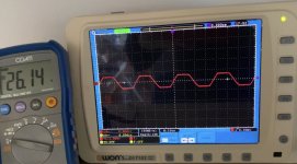
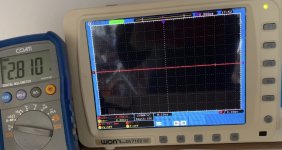
This is what I mean. The yellow is the rail voltage. It comes up first, then the rail-rail oscillation begins. I think there may be an issue (on some 21844 amps) if the oscillation starts as the rail voltage is coming up. The delay allows all of the supplies to stabilize before the driver IC is enabled.
http://www.bcae1.com/temp/ampstartup01.mkv
http://www.bcae1.com/temp/ampstartup01.mkv
This is what I mean. The yellow is the rail voltage. It comes up first, then the rail-rail oscillation begins. I think there may be an issue (on some 21844 amps) if the oscillation starts as the rail voltage is coming up. The delay allows all of the supplies to stabilize before the driver IC is enabled.
http://www.bcae1.com/temp/ampstartup01.mkv
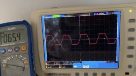
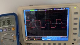
I have performed the test that indicates me. the result on all 4 sides (4 irs21844) is identical.
Attachments
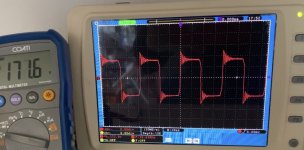
I'm not sure what I'm seeing in your video. I don't think that the rail-rail oscillation should not start until the rail voltage is steady (I could be wrong. I've never really checked this).
The rail-rail oscillation should not go beyond the rail if you took the signal from the input to the output filter inductor.
The r-r oscillation should also be centered between the rails and not have DC.
The rail-rail oscillation should not go beyond the rail if you took the signal from the input to the output filter inductor.
The r-r oscillation should also be centered between the rails and not have DC.
#34:
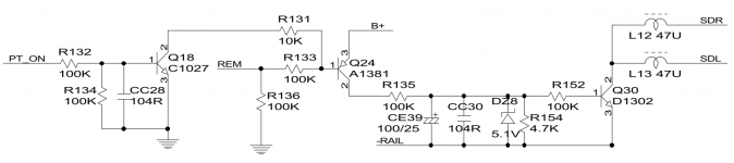
I don't repair the 21844 amps often so I've never really had to look at this circuit. The attached is a generic circuit from a 2-21844 amp.
It appears that the Q30 is switched on by Q24 when B+ is applied. When remote is applied, the PNP (Q24) switches off an allows CE39 to discharge through R154. When the capacitor voltage drops below the threshold voltage of Q30, Q30 releases the SD lines, allowing them to pull up and enable the 21844 driver ICs.
Start a new thread or email me if you have more questions regarding this.
Attachments
An externally hosted image should be here but it was not working when we last tested it.
https://vk.com/photo-110216664_456241265
Hello Perry
If we turn on this segment of the circuit regulates the launch of IR21844, then how to make their work more stable? Indeed, in 90% of cases, the problem of breaking them down is most likely in this particular piece of the scheme.
If, when turned on, we discharge 100Uf through a 4.7k resistor, then how best to proceed for a longer run. Most often, in my practice, the amplifiers burn during the time when the car engine is started (most likely a voltage jump occurs) and the driver fails and the amplifier loses part of the power switches (24N40). It may be worthwhile to increase the driver launch at the time of voltage stabilization in the power supply by increasing the resistor 4.7k, for example, by replacing it with 10k. will we get ip21844 launch about 2 times longer?
But how to be at the time of shutdown (amplifier) driver? How to make the STOP of the SD line more fleeting?
I also saw on the driver boards there are drops in the 0805 case along the line L-in and SD. this is L5, L3, L4, L2, L1. Most interestingly, I noticed that on the CT-SOUND amplifiers there are DIODES in place of these throttles along the line SD.
Do you have any idea?
Last edited:
- Status
- This old topic is closed. If you want to reopen this topic, contact a moderator using the "Report Post" button.
- Home
- General Interest
- Car Audio
- blowing output transistor DD Z2