Hello everyone
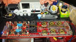
I just finished repairing a GZPA-10000SPL-HC amplifier.
I performed all the routine checks and it was enough to replace all the IR21844S + Diodes of VB pin + all the output mosfets.
Originally, the output mosfets used were FDA24N40F, but to be more safely, I decided to install the FDA24N50F because the rail voltage is very high (+/- 192volt at 14volt) and 400volt mosfets seemed very tight.
Since the new mosfets are a bit more difficult to drive, I have reduced the gate resistors from 47 to 33ohm.
First ignition (with only 1 mosfet per side for each stage and a 47 ohm resistor at the output of the amp), everything is OK, all 4 stages of amplification work and switch to about 125khz (normal switching frequency for these types of amplifier) but I noticed that after 30 seconds of operation, the mosfets were heated, not much, but I could feel very well with the finger (all the mosfet installed heated the same way, no one warms more than others) I thought to reassemble 47ohm gate resistors, but the result does not change; on the contrary, the amp absorbs more current from my power supply.
So, returned to 33R gate resistor and installed all 24 output mosfets and the situation is much improved, all the mosfets heat up little, really just after 1 minute of operation without input signal and always with the 47ohm resistor at the output.
I was thinking that probably, since it is a version HC amplifier, since the rail voltage is particularly high, it was normal for some heating (I'm also thinking that I just have to install everything in the heatsink without making too many problems); on the other hand, I have repaired many lower-rail amplifiers and the same type of circuit, where the mosfets do not heat up at all.
What do you think?
Hi Tom,Mario,
Did you resolve this issue? or is it still open? I have a similar issue, with an amp that uses FDA24N40F, and the rail voltage is close to max.
I am considering installing the FDA24N50F's in there place.
in the end I mounted the board inside the sink, obviously the problem disappeared because the heating was really minimal, something that did not give me much concern (the fact remains that other amplifiers with the same design that I have fixed, have not had this problem").
In order to deepen the question then, I bought a digital laser thermometer, and thanks to this I was able to discover that the high side mosfets warmed slightly more than the low side ones, only in a second moment I realized that the heat generated was not from the mosfets themselves , but from the huge resistor 47ohm 10watt installed in the immediate vicinity of the mosfet high side, its heat was transmitted to the board and this transmitted to the mosfet, for this reason I have reason to believe that the low side mosfet warmed because they were in tight contact with the true source of heat.
However there is also another very important factor, the rail voltage, 400vdc rail to rail are a enormity that in the other amplifiers I have not met (the maximum was +/- 125-130vdc) so it would not surprise me a bit of heat .
I repeat, once everything is mounted in the heatsink, the problem is completely gone and the amp works perfectly.
If you also want to install the FDA24N50F, you will need to adjust the gate resistors (keeping in mind what you have now).
My ground zero 10000hc has a rail extremely close to the maximum (+/- 197v).Do you know if that has a regulated supply?
This is because it is the "HC" version, in fact the power supply is not regulated and the working cycle on the gate of the power supply mosfet is always at 49%.
In your case, it depends on the amplifier.
What amp is it?
Generally, a regulated power supply will have a variable work cycle on the mosfet gates (very short when the amplifier is simply switched on, without producing output power, typically 15-20% and can reach 49% if you lower the power supply voltage below 12 volts).
This uses a design really similar to mine, difference in the triple power terminal block (mine has 2) ....It’s a Sundown 7500
Since my amplifier is produced in 2 versions, GZPA-10000SPL & GZPA-10000SPL-HC and the only difference between the two is precisely the stabilization of the power supply, which leads to having a lower rail in the first (while it is only in function, without sounding) that is kept stable through regulation during periods of high absorption.
To find out if yours is regulated or not, you would need an oscilloscope, and see if you have a full duty duty cycle (49%) or short (10-20%) signal on the power mosfets.
Unfortunately, when the output mosfets are not installed, the rail voltages rises a lot because it has nothing that forces it to go down.
Hi, I want to resume this old post to ask you for help.
When I repaired this amp, I tested it with a power supply of 13volt, the amplifier worked well, it came out with a lot of power (5.6kw).
I never mounted it in the car because I did not have time, but last night, I reconnected it on the workbench, increasing the supply voltage from 13 to 14.5 volts (to simulate the power supply voltage of the car when it is running ) and the amplifier has started to emit a small noise in the subwoofer that gradually disappear after about 4 seconds, but the problem is that after 20 seconds of operation (idle) a mosfet (FDA24N50F) and the related ir21844s exploded, the rest is intact.
How is such a thing possible?
I increased the supply voltage to simulate the presence of the alternator, so I assumed it was a normal and acceptable operating condition.
With the 12volt supply voltage the rail reached +/- 197v, so I suppose that at 14.5 the rail has risen, but still remains in a safe zone.
What do you think?
No, during other failures, all 4 group are exploded....During other failures, has the same output group and IC failed?
Are you buying parts from an authorized distributor?
Are the ICs being shipped in an air-tight package with desiccant and a moisture indicator card?
Sometimes, all sections fail because the ICs short internally and drive high voltage back to the other ICs. If you repair it again, It could be that there is a problem with the group that failed this time causing the failure of all previously.
Did you check the drive directly across the gate and source to see if the drive signal was precisely the same for all groups, high and low sides?
An intermittently shorted inductor is also possible. It could be that the higher voltage is reaching the point where it will arc across. I've also seen some that were temperature sensitive and as soon as the inductor heated up, it would short.
I bought both the mosfets and the ICs from MOUSER and the ICs were packs just like you indicated.Are you buying parts from an authorized distributor?
Are the ICs being shipped in an air-tight package with desiccant and a moisture indicator card?
Sometimes, all sections fail because the ICs short internally and drive high voltage back to the other ICs. If you repair it again, It could be that there is a problem with the group that failed this time causing the failure of all previously.
Did you check the drive directly across the gate and source to see if the drive signal was precisely the same for all groups, high and low sides?
An intermittently shorted inductor is also possible. It could be that the higher voltage is reaching the point where it will arc across. I've also seen some that were temperature sensitive and as soon as the inductor heated up, it would short.
Perry, I bought this broken amp.
When I analyzed it for the first time, all the groups were short-circuited.
In addition to the clearly exploded mosfets, there was nothing else to suggest an intermittent short.
All the inductors are perfectly clear, of the same color (bright red) and on the whole PCB there are no burn marks ...
All gate resistors were perfect, but for safety I replaced them with new ones, all the pulldown resistors were perfect and all the other components around them were normal.
The power supply section was the only part that had not exploded, but this is perhaps normal, because it is really oversized.
I proceeded to the repair without any problem ...
I removed the old IRS21844 and reinstalled the driver board without the ICs, to see (with the oscilloscope) if on the pads 1 of each IC there was a correct signal (injecting a loud audio signal at 100hz) using the RCA shield as a reference , everything was in the norm.
I installed the new ICs and I checked the signals directly on the gate pads (without the mosfets installed) using the source of those pads as a reference and everything was normal on the low side, the high side would be automatically generated after installing a handful of mosfet.
I installed some mosfets with caution and precautions and all went well, except for a slight heating of the mosfet that disappeared after installing ALL the mosfets.
Coincidentally, I tested the amplifier always with a power voltage never higher than 13volt, but yesterday I thought to simulate the power supply voltage that you would have in the car (14.6) and without even starting to make it sound, exploded.

Unfortunately I did not have the chance to measure the rail when I was at 14.6v because everything was so fast and fleeting, but I'm thinking that in the car we always have a supply voltage higher than 14volt when the amplifiers are simply switched on.
Last edited:
Mario,
I just had a similar issue with a Sundown amp. In my case, the power supply and amplifier where able to be separated. It makes it easy to repair the power supply, esp when the amp appears to be ok.
The rail voltage when separated was +/- 190ish volts, which I also thought was to close to the maximum for the 24N50Fs. But when I joined the 2 sections again, it wasn't near that voltage. I don't remember what it was, but it was low enough for me not to think it was a border line issue.
That being said, this amp had failed twice for exploding Mosfets, (as you have), I replaced them and the IR21844S's, but this amp had been repaired by AmpLab several weeks before I got it, and one of the inductors was removed and re-glued to the mother board. I removed the coil to find that there was scrap mark, through the copper land, under the coil, that contacted the coil. I wish I took a picture of it, because it's an example to a failure that I have found on several amps.
There was a clear ring mounted under the coil, that was to small for the coils landscape, which contributed to the unwanted contact. I repaired that and re-RTVed to the MB.
Since than, the issues have not re-occurred. and believe me, this guy tested it.
On a side note, those amps draw over 200 amps on initial start up, I have a 100 amp supply, and a 850 amp car battery attached, when I turn them on.The power supply reads 100amps when I turn it on. beware of that.
I have often heard about these problems, but we must admit that this fault should come out at any power supply voltage and not only at 14.5volt.Mario,
I just had a similar issue with a Sundown amp. In my case, the power supply and amplifier where able to be separated. It makes it easy to repair the power supply, esp when the amp appears to be ok.
The rail voltage when separated was +/- 190ish volts, which I also thought was to close to the maximum for the 24N50Fs. But when I joined the 2 sections again, it wasn't near that voltage. I don't remember what it was, but it was low enough for me not to think it was a border line issue.
That being said, this amp had failed twice for exploding Mosfets, (as you have), I replaced them and the IR21844S's, but this amp had been repaired by AmpLab several weeks before I got it, and one of the inductors was removed and re-glued to the mother board. I removed the coil to find that there was scrap mark, through the copper land, under the coil, that contacted the coil. I wish I took a picture of it, because it's an example to a failure that I have found on several amps.
There was a clear ring mounted under the coil, that was to small for the coils landscape, which contributed to the unwanted contact. I repaired that and re-RTVed to the MB.
Since than, the issues have not re-occurred. and believe me, this guy tested it.
On a side note, those amps draw over 200 amps on initial start up, I have a 100 amp supply, and a 850 amp car battery attached, when I turn them on.The power supply reads 100amps when I turn it on. beware of that.
Besides, I had no other problem that left me thinking of an anomaly.
Before mounting the entire PCB in the chassis, I turned on the device to check if there were any abnormal heat and everything was normal.
If I had an inductor shorted or touched some track on the PCB, surely I would have had an immediate explosion or the mosfets would have warmed up or there would have been groups that warmed up more than others.
I repeat, everything was normal.
I'm thinking of a defect of some mosfet, but I'm very hard fought, because at the same time, there is something that makes me think that at 14.5volt, the rail has gone too far, but I have no certainty.
hello) specifically in this model I rewind by two turns with each transformer power. FDA24N40F to 47om in the left gate. It's okay. Food does not reach dangerous values. (+ _- 145B)
Don't do that anymore! You had an amplifier with a power of 10 kW, and it became 5 kW. 5 kW you rewind!
Remove this post so that people do not go astray!
I bought both the mosfets and the ICs from MOUSER and the ICs were packs just like you indicated.
Perry, I bought this broken amp.
When I analyzed it for the first time, all the groups were short-circuited.
In addition to the clearly exploded mosfets, there was nothing else to suggest an intermittent short.
All the inductors are perfectly clear, of the same color (bright red) and on the whole PCB there are no burn marks ...
All gate resistors were perfect, but for safety I replaced them with new ones, all the pulldown resistors were perfect and all the other components around them were normal.
The power supply section was the only part that had not exploded, but this is perhaps normal, because it is really oversized.
I proceeded to the repair without any problem ...
I removed the old IRS21844 and reinstalled the driver board without the ICs, to see (with the oscilloscope) if on the pads 1 of each IC there was a correct signal (injecting a loud audio signal at 100hz) using the RCA shield as a reference , everything was in the norm.
I installed the new ICs and I checked the signals directly on the gate pads (without the mosfets installed) using the source of those pads as a reference and everything was normal on the low side, the high side would be automatically generated after installing a handful of mosfet.
I installed some mosfets with caution and precautions and all went well, except for a slight heating of the mosfet that disappeared after installing ALL the mosfets.
Coincidentally, I tested the amplifier always with a power voltage never higher than 13volt, but yesterday I thought to simulate the power supply voltage that you would have in the car (14.6) and without even starting to make it sound, exploded.
Unfortunately I did not have the chance to measure the rail when I was at 14.6v because everything was so fast and fleeting, but I'm thinking that in the car we always have a supply voltage higher than 14volt when the amplifiers are simply switched on.
Add a photo please
Add a photo please
Attachments
- Status
- This old topic is closed. If you want to reopen this topic, contact a moderator using the "Report Post" button.
- Home
- General Interest
- Car Audio
- GZPA10000SPL-HC repairing