My ppi 4125 is making a poping noise intermittently and harmonic distortion in only that channel.I have removed rca cables and the noise is still there with poping.I switcheddar the speakers and noise follows. Put a volt meter on that chanel and it is fluctuating bellow 1 volt and up to 2 volts ,no rca even hooked up.and the other channels maintain 0 output.the amp has never been split open what do you think the issue is and should I take a peak inside to inspect no power to it while I do it
Noise in front right ch of precision power pcx 4125
Thank you for the reply about my ppi pcx 4125.I apologize for my ill typing and computer skills. Again I am looking to get it fixed but am not sure if I can do it myself. I looked at your sight and it is alot to absorb at once but it is very informative .I looked at the section that talked about op amps and how they controle the signal or clean it up in the circuit. I still am trying to wrap my brain around it all ,I just have to read more and over again and again .I did open the amp up and looked inside and it was very clean.I also removed the 4 screws that hold down the driver board to see if anything needed cleaning but all seemed well besides a little corrosion on the hp lp switches on the solder pin side of the board.any ideas on were to start if I try to trace the issue and replace the part or fix the most likely tiny electrical component that is causing the problem,if that is the problem
Thank you for the reply about my ppi pcx 4125.I apologize for my ill typing and computer skills. Again I am looking to get it fixed but am not sure if I can do it myself. I looked at your sight and it is alot to absorb at once but it is very informative .I looked at the section that talked about op amps and how they controle the signal or clean it up in the circuit. I still am trying to wrap my brain around it all ,I just have to read more and over again and again .I did open the amp up and looked inside and it was very clean.I also removed the 4 screws that hold down the driver board to see if anything needed cleaning but all seemed well besides a little corrosion on the hp lp switches on the solder pin side of the board.any ideas on were to start if I try to trace the issue and replace the part or fix the most likely tiny electrical component that is causing the problem,if that is the problem
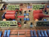
I am not sure exactly what the driver boards are but I did see 4 little cards inside that I am assuming are those .I removed the 4 screws that hold down a board suspended above the the main board with all the pots and switches attached to it . I am going to take the amp apart again and get some serious pictures so I have reference of everything.
Sometimes, the carbon resistors behind the large driver transistors begin to fail and cause the problem you described. You should know that, unless you're very lucky, these driver boards are VERY difficult to repair because the silver traces and pads have begun to deteriorate due to age. Do not solder on them except as a last resort.
In the linked image below, you should read 100 ohms for both the A and B probe locations.
http://www.bcae1.com/temp/ppidriverboardresistoroverlay01.swf
In the linked image below, you should read 100 ohms for both the A and B probe locations.
http://www.bcae1.com/temp/ppidriverboardresistoroverlay01.swf
View attachment 713501
I did finally get access to the link you gave me with some help for the output driver board resistor overlays. I was able to test them with my meter set at 200 ohm setting and tested each one . The top left, top right and bottom right tested at 100 ohm perfect.the bottom left board tested at 100.2 ohms .this is the A probe resistor as marked in the diagram you gave me. Now for the B probe test I tested the top left board at 100.2 ohms ,top right board at 100.2 to 100.3 ohms,bottom left board 100.5 ohms and bottom left 100.3 ohms . Is that small of a fluctuation enough to cause the intermittent noise. Like I mentioned only 3 of the board resistors tested at 100 ohms perfectly . Thank you for your patience .
Attachments
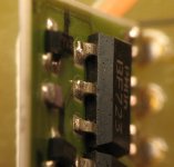
I am going to have to grab a magnifying glass to look a little closer .what I can see is poor soldering in some places and the feet are not lined up very well with the solder pads for the transistors. I am going to get a glass to look closer at the and I will get back to you pretty soon on what I can see. From the looks of the entire amp these boards seem to be the worst looking things in the amp ,there is tarnishing on back of boards and poor soldering on them .if the boards are the issue I have located new boards that are aftermarket and rebuildable from amp dr. Have not been able to find exact or new origional.
Wow! I put the glass on these areas and low and behold there is alot of cracks in the solder joints. I took my prob while looking to see if I could budge the feet of the transistors and it looked as if it move a little, didn't want to go to hard on it but it is apparent that these joints are sh$t . You had mentioned that these boards are not repairable or is that just the resistors you mentioned. Can these feet be re soldered back on or touched up.
Some of the boards are repairable but it's hit and miss. If you try to resolder these, just apply the least amount of heat possible and if you have solder without flux, use it. If you solder a marginal board like you would a good board, the silver traces will sometimes pull up due to the action of the flux. This will make them difficult to repair. If you solder them, the safest thing to do is to do what would normally be considered a poor job.
Just solder the board for the channel that's causing you the problem.
Just solder the board for the channel that's causing you the problem.
- Status
- This old topic is closed. If you want to reopen this topic, contact a moderator using the "Report Post" button.
- Home
- General Interest
- Car Audio
- Ppi 4125 rch intermittent poping