I found the problem. Will the amplifier produce an output signal at the speaker terminal with only one side? If not i thik that neither driver board is working. Or i can find the drive signal. Should i have both the p and n channel transistors out of curcuit when checking for the drive signals?
I found the problem. Will the amplifier produce an output signal at the speaker terminal with only one side? If not i thik that neither driver board is working. Or i can find the drive signal. Should i have both the p and n channel transistors out of curcuit when checking for the drive signals?
This was my intention in my post #15. You can test the board/s with or with out the N and P channel mosfets. It may save you some grief by removing all of the N and P channel Mosfets!
I Believe that D3 is the main culprit, but it doesn't hurt to have the parts to rebuild the boards on hand in the event there may be other failures.
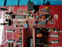
R18 is a 3.3KOhm 2 watt resistor, tied to a 1N4742 12v zener diode (D3). This circuit sets up a 12v reference for the over current protection circuit. My guess is you have a problem with the driver board.
Remove the suspected bad driver board and with the opposite side driver board still in place check to see if you have drive to the other side. If so, remove good board and install in place of suspected bad board. If swapping the boards proves good, I can walk you through repairing the bad board. Post pics of the driver boards when you have removed them, so that I can edit and show you possible failed parts.
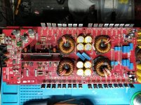
With the remaining driverboard #2 I n curcuit I have hi and low side drive. I also on diode test tested each set of pads with both driverboards in curcuit. I rebuilt the powersupply some of the transistors legs were cracked at the base. Repaired all the output torrids. And I'm rebuilding the entire output section with matching p+n channels transistors. I ordered a diode for d3 is a 1N4742? amp was the original. I thought it was a 1N472A I have 4742 12v diode for sure.
Last edited:
With the remaining driverboard #2 I n curcuit I have hi and low side drive. I also on diode test tested each set of pads with both driverboards in curcuit. I rebuilt the powersupply some of the transistors legs were cracked at the base. Repaired all the output torrids. And I'm rebuilding the entire output section with matching p+n channels transistors. I ordered a diode for d3 is a 1N4742? amp was the original. I thought it was a 1N472A I have 4742 12v diode for sure.
The A suffix denotes a 5% tolerance as opposed to the 10% tolerance of the zeners marked 1N4742. The schematics call for a 1N4742. Either should do.
i have a problem somewhere else. the audio isnt present at the speaker terminals. Just some strange drive wave. The diode came in and i repalced it and checked all the transistors. I will have to pull them all, Should i just replace them all with bd139-140? Have the originals as well. I'll check the other components listed above, for open or short curcuits. All new Output P and N Channel outputs have been installed. I thought i had it correct.
Last edited:
Do you have an oscilloscope? If not a Voltmeter will do.
With out any signal applied, check to see if you have drive to the output mosfets. With a scope (scope ground to signal ground and probe to anyone of the output mosfet gates) you should see a squarewave. You only need to check 8 mosfets (one in each bank, for on each side).
With a DC voltmeter, measure across the output mosfets, outside leads(source to gate). You should see 5 volts DC, again only 8 mosfets is necessary.Be sure to monitor the current draw if possible, otherwise take one or two measurements at a time, and shut down amp. These amps can be unstable outside of the chassis, and thermal runaway will cause shorted output or outputs and power supply mosfets.
If you have drive (squarewave or 5VDC) apply signal, a 50hz test tone is recommended, otherwise any audio source will do. With a scope or AC Voltmeter, either one will have signal ground as a reference,you will have to turn the board upside down to have access to the inner leads of the output inductors, where you place your probes.Check the outer leads as well for a modulated waveform(You can see this with a scope much more clearly, but an AC meter will show a varying voltage)If you have drive and the audio is passing through the preamp board, you should see audio here. If that's the case, the relay may not be passing audio, which could be the relay itself, cracked or cold solder joints on relay, or relay turn circuit.
The takeaway here is that if you have drive to the outputs, the sub boards are good! And as long as the preamp is passing audio to the main board,and you have modulation the Class D section is good and the relay is the last link in the chain.
If you have drive and audio to the main board but no modulated audio at the output,the next thing to check is the Class D circuit.I will get into that if necessary.
If possible, post screen shots of scope and post the AC and DC measurements you take at the test points I mentioned.
Sorry, its a lot to chew on, but these amps are very complicated and awkward to work on. Take it step by step and you should be able to crack it, I think your more than half way there!!
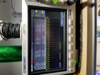
Yes I have a scope, just not that well trained to what I am looking at on it. I know to look for drive wave forms in ps. And I can get this on accept coupling, at the high side gate resistor with signal. 40hrtz 4v sine wave. And on a voltmeter they have 7.2vdc across them. Relay is clicking once. Some of the transistors on the driver boards are reaching 112°f c3503 the output remain cold as do the ps mosfets. I have a good 40hrtz on the pin labeled out on the preamp board.
Attachments
Last edited:
For reference. Before I put the outputs in I had a drive signal. A small squarewave without signal. With then outputs installed I can't seem to get it to display. I believe it's just still muted. I think it's the relay now. I have these in stock.
Attachments
Last edited:
Post a picture of board from the bottom side. I will highlight test points.
Also, remove preamp board and you will find U907,U908 and U909, this is the Class D circuit. Take a good quality picture of the Class D circuit and I will point out the test point you can probe with your scope
Also, remove preamp board and you will find U907,U908 and U909, this is the Class D circuit. Take a good quality picture of the Class D circuit and I will point out the test point you can probe with your scope
R117 is 22ohms. The relay I swapped out today, since I had them on hand. Same result. No signal at the output teansitors, and I have the signal coming out of 104 and at the out pin of the preamp board. The fault must be either the class d section or the driver boards. They are the only other two sections in between the preamp and the output transistors.
Attachments

For reference. Before I put the outputs in I had a drive signal. A small squarewave without signal. With then outputs installed I can't seem to get it to display. I believe it's just still muted. I think it's the relay now. I have these in stock.
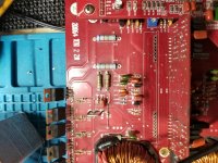
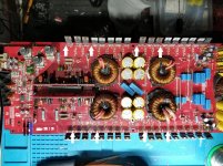
The attachment are the test points for top side of board.
White arrows- These are the gate resistors(side connected to the mosfet gates)
You should see something similar to the power supply drive with your scope,do not apply signal. Post screenshots from all eight test points.
Blue arrow- Of course this is the audio from preamp board. with the 40hz Test Tone applied, post a screenshot of this point
Black arrows- This is the +/-12 volt test points. These voltages are necessary for the preamp board and the Class D circuit and if one or both are absent you will not have output. Check with a DC Voltmeter and post if you haven't check them.
Attachments
R117 is 22ohms. The relay I swapped out today, since I had them on hand. Same result. No signal at the output teansitors, and I have the signal coming out of 104 and at the out pin of the preamp board. The fault must be either the class d section or the driver boards. They are the only other two sections in between the preamp and the output transistors.
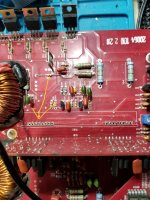
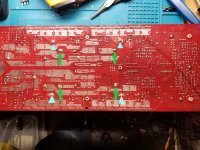
These are the test points for the bottom side
Light Blue triangles- Test points for inputs to the output inductors. With a scope and signal applied, you should see a modulated squarewave. Without signal you should see an amplified version of the drive waveform to mosfet gates.Post two pics with and w/o signal.
Green arrows- Test points for the outputs to the output inductors. With a scope and signal applied, you should see the amplified 40hz test tone which can be varied with the gain pot.
Attachments
- Status
- This old topic is closed. If you want to reopen this topic, contact a moderator using the "Report Post" button.
- Home
- General Interest
- Car Audio
- Kicker zx2500.1 power issues