An externally hosted image should be here but it was not working when we last tested it.
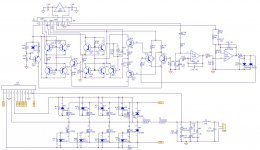
I'm trying to repair this amplifier, at first all output mosfets were blown, i replaced them but they were heating up so i checked driver circuit and now as soon as i put in mosfet back it shuts off.
Checked the mosfets again and they were fine, not shorted or anything.
I checked all transistors and replaced few, drive signal is ok (i also replaced TL072), when i put mosfets in i get signal on output but it pulls a lot of current and protection kicks in.
What could cause that? What should i look for?
Last edited:
To upload photos click the following:
Go Advanced
Manage Attachments
Browse
Upload
Repeat as needed
Preview post to see how the post will look.
Click Submit Reply to send it to the forum.
With no outputs in the circuit, drive a low frequency (50-100Hz) signal into the amp. Do you see a drive signal on all of the output transistor gates?
I didn't look at all of the diagram you posted since it's just a clone type board and common in many amps but the 1N4148 that you have in location D114 is a 5.6v Zener.
Generic Asian Clone driver board RE and Clone
Thanks for info.
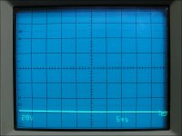
Without input i have 0v on top bank (on schematics) and 15v on lower bank, with input signal there is clear signal on each bank (tried to change freq and signal also changes). Driver circuit is on main PCB with everything else, not one like you posted, D114 is zener diode like you said and there is 5.84v across it.
Without input i have 0v on top bank (on schematics) and 15v on lower bank, with input signal there is clear signal on each bank (tried to change freq and signal also changes). Driver circuit is on main PCB with everything else, not one like you posted, D114 is zener diode like you said and there is 5.84v across it.
Attachments
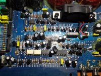
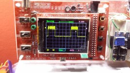
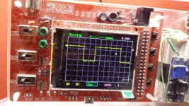
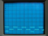
Vgs on high side (Q23-Q27, not sure if that's high or low) seems to be a bit "distorted" i guess. Also there is 4.5v DC on speaker outputs when signal is present (without mosfets and load).
Rail voltage is 77.5v, measured both rails and they seem to be ok.
Rail voltage is 77.5v, measured both rails and they seem to be ok.
Attachments
As a side note, if that DSO138 is like mine, it's only good for audio frequency signals. The square wave drive signals will look more like sine waves at anything over about 20kHz.
The high side will clean up if you connect a 1000pf cap across the gate and source of the FET pads.
What are you using for a power source?
The high side will clean up if you connect a 1000pf cap across the gate and source of the FET pads.
What are you using for a power source?
If i measure between ground (0v) and one side of fets gate i get peak at around 70v (low side of signal is around 55v) on other side of fets its from 0 to around 15v (like on previous pictures). If i measure from negative rail (-77.5v) to gate of one side of fets i get same thing but from around -70v to -60v (could be -77.5, scope is not that precise) on one side and 0 to -15v on other side.
I'm using bench psu (switching regulator, 14.4V 3A, no adjustable current limit but as soon as i put fets in it pulls 3A, tried with second psu and drawed 20A and fuse on dmm burned)
I'm using bench psu (switching regulator, 14.4V 3A, no adjustable current limit but as soon as i put fets in it pulls 3A, tried with second psu and drawed 20A and fuse on dmm burned)
You need to be aware that when the scope ground is connected to the negative rail (checking low-side drive), all grounds on the scope have full negative rail voltage on them. If you check the high-side when the FETs are in the circuit, the grounds of the scope will have full rail-rail voltage on them.
Where did you buy the FETs from?
Are all of them brand new (no used ones from the original set)?
Are they IRFB31N20Ds?
Where did you buy the FETs from?
Are all of them brand new (no used ones from the original set)?
Are they IRFB31N20Ds?
I replaced all 8 mosfets (IRF3415) and amplifier worked but it was heating one side of mosfets (not always, sometimes it was cold) so i went to check drive circuitry and can't get it to work since then. All mosfets were bought locally for around 25$ so i don't think they were fake, they all still work, all from same batch (same characteristics when tested with tester).
It feels like mosfets are trying to drive something on output but don't know what, or they aren't balanced, i don't know how to explain.
It feels like mosfets are trying to drive something on output but don't know what, or they aren't balanced, i don't know how to explain.
Not to make them to work, to load driving circuitry because it seems like as soon as i put in mosfets and load it it doesn't work properly.
I'm located in Croatia, i was searching for sites but almost nobody ships and those that ship have shipping fee that's more expensive than mosfets.
For some reason resistors at gates are 4.7 ohms and not 47 like on datasheet, does that make any difference?
I'm located in Croatia, i was searching for sites but almost nobody ships and those that ship have shipping fee that's more expensive than mosfets.
For some reason resistors at gates are 4.7 ohms and not 47 like on datasheet, does that make any difference?
Isn't each side only seeing one rail voltage (77.5v)?
I also found out D37 is shorted, i'm gonna replace that tommorow.
It's weird since amp was working with those mosfets for a week but it was getting hot (drawing 5A at idle), gain was set to 34v (about 300W at 4 ohms, i couldn't draw more from ATX psu), i wouldn't touch it but i just had to check what was wrong to cause it heat up like that, i probably burned something when i was probing drive circuitry. Again all 8 mosfets are still ok, none of them burned or anything.
If i don't figure it till the end of the week i'm gonna look into getting 31N20D.
- Status
- This old topic is closed. If you want to reopen this topic, contact a moderator using the "Report Post" button.
- Home
- General Interest
- Car Audio
- Ground Zero Amplifier Repair