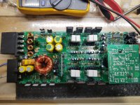
This 300/4 I had a cracked diode in zd1 only marking on the part was (pH 0.5v). I need to know what that is. The remote is not working. If you apply b+ and ground it Powers up and draws .65 amps of current, so remote has no effect. It may have something to do with the zenner diode. I can't seem to find the correct one.
Attachments
Check RP87-O Ohm resistor, tied between speaker and power grounds. An open resistor
may cause no output.
Check Q3-2N4403, Q31-2N4401, Q17-2SB772 and P39-4.7 ohm resistor. If the resistor is open Q17 may be shorted C-E and the other transistors may have failed.This will bypass the Remote Turn On and power up with out remote.
I will attempt to post your pic with edits pointing out the two circuits.

I don't have a b772 in stock. I changed the other two transistors and the 4R7 was open. I replaced that as well. The 0ohm resistor reads .3ohms.
Still the amp Powers up without remote voltage.
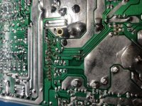
This peice of trace was burnt when I first opened the amplifier. I repaired it with a small jumper for now.
Still Powers up without remote voltage.
Still the amp Powers up without remote voltage.
This peice of trace was burnt when I first opened the amplifier. I repaired it with a small jumper for now.
Still Powers up without remote voltage.
Attachments
The resistance should not rise, and should be a dead short.
Check the resistance from speaker ground terminal to one side of the RP87 0 ohm resistor, and then speaker ground to the other end. Repeat this measurement with the power ground terminal.
Recheck and/or replace the RP87-0 ohm resistor.
You can temporarily place a jumper from Spkr Ground to Power Ground to see if the amp powers up with the remote. The T1 Transformer secondary center may be used as a convenient point for the spkr ground connection. Again, this is only temporary and the jumper between grounds should be removed after testing.
Apologize for the late reply.
Take a look at P23 & P29. You will find them on the main board, underneath the input board. Depending on the rev of this amp, the values may be as follows: P23-27K Ohm or 12K Ohm, P29-180K Ohm or 1N5225 (3V zener). The 12K Ohm and 3 volt zener where an engineering change to increase the remote output current to trigger external relays.
P23 & P29 are tied between the Hi Level Ton (R21,R22-Voltage divider across the Front Left channel RCA and Q31 Base-Emitter circuit. I'm don't know what failure in these two components that would cause the remote to trigger falsely, but its worth looking at. Also, look for open or lifted traces, solder bridges.
Is it possible you where applying signal when testing? This would cause the amp to turn on and is the the alternative to a head unit without a remote turn on lead.
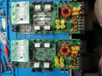
I just received another one of these amps. This one just power cycles in protection. I checked everything mentioned above posts. And these amplifiers don't seem to have the mentioned curcuit. All resistors are in tolerance 0 ohms and 4.7ohms and both have good transistors. All other resistors match. Would it be any of these capacitors?
Attachments
To keep things clear, lets call the amp that you initially started this thread for, Amp 1 and the most recent amp, Amp 2.
Amp 2-Typically, the cause for this amp to go in and out of protection is a shorted output device or transistor/s in the driver stage. Check the output transistors with an ohmmeter, if you find a short, remove the output transistor and check the transistor and the locator of removed output. I would replace both B688 and D718 if one is shorted.
Amp 1- Referring to my post #16, the circuit I describe will be on both amps, but the P23's resistor value and P29 being a resistor or a zener diode depends on the rev or if it has been revised in our shop. Do you mean to say that P23 and P29 are resistors with the values I posted? 27 ohm and 180k ohm respectively.
If you can get Amp 2 working, it may serve as a template to compare against Amp 1, to better troubleshoot Amp 1.
- Status
- This old topic is closed. If you want to reopen this topic, contact a moderator using the "Report Post" button.
- Home
- General Interest
- Car Audio
- Kicker 300/4 power supply issues.