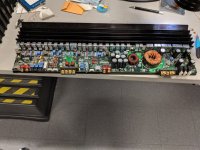
My personal sub amp in my car blew a set of fuses about a month ago. It is a Zapco AG750. The AG and reference lines are identical besides the graphics. Rather than just replacing the fuses and reinstalling it to try it out again, my itch to open it up got the best of me. I did end up replacing the fuses and then checking it on my test bench. I did not find anything wrong with it, so I must have accidentally shorted the speaker wires at some point when I was moving my sub in and out of the trunk with the amp on. The only thing that I found was wrong with the amp is the cooling fan had a seized bearing. I already had the amp apart and on the bench so I decided to do some upgrades and refurbishing. I will list below all of the items I changed along with the originals. The amp itself is almost 20 years old, so I figured some of the caps are probably getting up there in age even though I had no reason to suspect any had actually failed. I wanted to upgrade the opamps inside also. Again, no reason that the current parts were insufficient, but I had the itch to upgrade, so I went forward. I had a couple broken switches also that I was going to replace if I had to take the full board out anyway.
I am not responsible for any damage you cause to your own amp if you try this, but it was an entertaining experience for myself.
Fan:
Original: 6.3CFM 34.7dBA Jamicon JF0410S1H
Replacement: Sunon MF40101V1-1000U-A99
The replacement fan uses a much better bearing for longer life and less noise. This type of bearing also does better when mounted at an angle compared to the old sleeve bearing. Replacement fan is 8CFM at 27.3dBA. I had to splice in the new wires as it uses a connector to connect to the amp, but this was trivial. This was the only component that had obviously failed (seized bearing) in this entire rebuild.
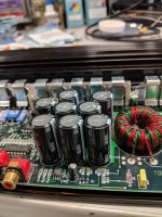
Input (primary side) capacitors:
Original: NRSZ 3900uF 25V 18mm x 31.5mm
Replacement: Nichicon UHW1E472MHD 4700uF 25V
The originals are actually pretty good on paper for how old they are. They were semi-long life low ESR capacitors. I really like the UHW series of Nichicon caps for power supply applications. They are long life and low ESR, so that is what I chose. For the same case size, I could also use 4700uF caps over the the standard 3900uF ones. Both were 105C caps.
Output (secondary side) capacitors:
Original: Nichicon PL 1000uF 50V 16mm x 31.5mm
Replacement: Nichicon UHW1H222MHD 2200uF 50V
Like the primary side, I went with the UHW series. For the same case size, I went from a 1000uF to 2200uF. The only thing I was concerned about with the increased capacitance was the snubber network on the secondary side. I checked the resistor (R84) with a thermal camera both before and after. That resistor got quite hot both before and after, but the difference between the two cap values was negligible. These resistors normally get hot in other amps also.
Gain/Crossover adjustment shafts
Original/Replacement: PIHER 6064 for the 2 trimmer pot version
I found what the original part is, but I could not find a suitable replacement. One company out in europe had them, but required at least a $50 purchase and I did not need anything else from them. I ended up having to swap shafts around so I had full control over the input section, but the output crossover is now missing a shaft.
Slide Switches
Replacement: Eswitch EG2315A DP3T
The EG2315 also works, but the switch actuator ends up flush with the case. If you want the actuator to stick out like the originals, the EG2315A is what you want
Crossover 1x/10x Push Button switch
Replacement: ESwitch PBH4UEENAGX with G004A end cap
RCA Jack
Replacement: Kobiconn 161-4220E
The footprint matches the original, however the red and white colors on the jack are reversed. I was going to replace mine just because the mounting screw hole above it was starting to get stripped out because it was plastic. I decided I would rather have the correct color order as the screws I had still held. The jacks themselves were in good condition
Speaker terminal block
Replacement: In Car Audio Terminal Block 4 Way Right Angled PCB Mount GOLD PLATED OM0449f | eBay
Ebay is the only place I found the specific block I needed. One of my mounting screws was broken off, so now was a good time to replace it.
Input / Low Pass Crossover Opamps
Original: TL072 and TL074
Replacement: OPA1678 and OPA1679
Changing opamps is one of the most divisive subjects when talking about upgrading amplifiers and preamplifiers. I am not going get into an argument about did I need to or did I not need to. I did not NEED to, I just WANTED to. The amp sounded great before, I just wanted to try something different. I chose the OPA167X series of opamps as they are a relatively new series from TI that are advertised as similar architecture replacements (or very close) to the TL07X series with much better performance. (Webinar - Precision Audio Op-amps and Headphone Amplifiers | TI Training). I found this series of opamp to be affordable enough and since this is mainly used in high impedance circuits, I wanted something that had superior bandwidth, slew rate, same JFET input, and lower current noise. As this is used in high impedance circuits within the amp, I cared a lot more about low current noise compared to voltage noise. The voltage noise is also lower, but I was more concerned with the current noise. In practice, the opamps worked well (in my opinion) as a drop in replacement, but I will describe more of that at the end.
Output/ High Pass Crossover Opamp
Originals: NE5532
Replacement: NJM4562M and NJM4562D (SOIC or DIP)
The NE5532 is a venerable opamp used all over the place in lower impedance circuits. The NJM4562 (and LM4562) is a decent on paper upgrade to the NE5532 with a similar internal architecture. I can get into why I picked this particular opamp more if someone wants, but I used some of the same criteria as the TL07X/OPA167X above to determine what I wanted to use. It is interesting to note that the TL07X was used in the low pass section and full range section, but the only the high pass section uses the NE5532. There could be an argument that this is not the best choice with some of the lower closed loop gains that are running in this circuit, but I have been running it for a couple weeks now with no issues. I do not use the high pass function right now, so some of the opamps are not even used in my particular use case.
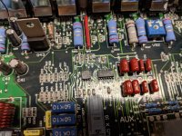
Coupling caps between preamp and amp sections (C73 and C88)
Originals: 220uF 50V
Replacement: Nichicon UKA1H221MPD
This is the coupling cap in the signal path, so I wanted to use an audio specific electrolytic capacitor. The Nichicon UKA series is the best 105C capacitor I could find in the same size and voltage as the originals. There are plenty of options of “fancier” caps in the 85C region, but I wanted to use 105C parts. I considered a smaller value poly cap such as the WIMA MKS2, but I did not want to use such a small value coupling cap when the original was a 220uF.
RCA input coupling caps
Originals: C108 C109 10uF NHE panasonic 50V 10uF 5mm x 11mm 2mm spacing
Replacement: Nichicon UES1E100MDM
This cap is only an 85C cap, but it is only on the RCA inputs. This cap is part of the high end “muse” series and I only needed 2 of them so I found it acceptable. This is also a bipolar cap with a 25V rating. The RCA inputs should never see anything higher than that. I also use the symbilink input in my setup which is DC coupled, so I do not actually even use this path other than when I did a bench test of the amp.
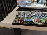
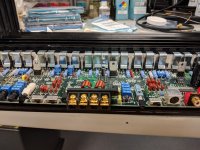
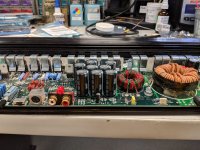
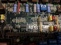
I removed the amp (along with it seemed like 100 transistor clips) to properly remove the old parts and install the new ones. After that was all said and done, I cleaned up all the old thermal grease and reapplied a fresh coat of dow corning 340 on the transistors and insulators. I reinstalled the board with all the new parts and then reinstalled all the transistor clips. I then bench tested the amp with the cover off using a thermal camera to check for any abnormalities. I checked each channel to full rated power at 4 ohms and saw nothing abnormal. I then did the same thing with a 4 ohm load bridged. Again everything looked good. I hooked up my test speaker to the amp afterwards and everything sounded as good as it could. My test speaker is just that… a test speaker that if it blows up I will not be too concerned. Judging the new opamp performance based off this speaker would be a fool’s errand. In truth, in my application I probably will not be able to tell much difference as I use it as sub amp for an Infinity Kappa Perfect 12.1. I reinstalled it in my car and reset the gains and crossover to be appropriate to my situation. The amp has performed flawlessly for the few weeks I have had it reinstalled. I hope to get another 10+ years out of it before I have to touch it again assuming I still have my current vehicle. I have some pictures of the finished product, but there is not much to see as everything was a drop in replacement of the original parts.
I know this was a long post, but hopefully someone can find it useful if for nothing else finding out what the original parts were on these amps and some potential replacements. I would guess most of the other AG and reference amps share similar architectures.
I am not responsible for any damage you cause to your own amp if you try this, but it was an entertaining experience for myself.
Fan:
Original: 6.3CFM 34.7dBA Jamicon JF0410S1H
Replacement: Sunon MF40101V1-1000U-A99
The replacement fan uses a much better bearing for longer life and less noise. This type of bearing also does better when mounted at an angle compared to the old sleeve bearing. Replacement fan is 8CFM at 27.3dBA. I had to splice in the new wires as it uses a connector to connect to the amp, but this was trivial. This was the only component that had obviously failed (seized bearing) in this entire rebuild.
Input (primary side) capacitors:
Original: NRSZ 3900uF 25V 18mm x 31.5mm
Replacement: Nichicon UHW1E472MHD 4700uF 25V
The originals are actually pretty good on paper for how old they are. They were semi-long life low ESR capacitors. I really like the UHW series of Nichicon caps for power supply applications. They are long life and low ESR, so that is what I chose. For the same case size, I could also use 4700uF caps over the the standard 3900uF ones. Both were 105C caps.
Output (secondary side) capacitors:
Original: Nichicon PL 1000uF 50V 16mm x 31.5mm
Replacement: Nichicon UHW1H222MHD 2200uF 50V
Like the primary side, I went with the UHW series. For the same case size, I went from a 1000uF to 2200uF. The only thing I was concerned about with the increased capacitance was the snubber network on the secondary side. I checked the resistor (R84) with a thermal camera both before and after. That resistor got quite hot both before and after, but the difference between the two cap values was negligible. These resistors normally get hot in other amps also.
Gain/Crossover adjustment shafts
Original/Replacement: PIHER 6064 for the 2 trimmer pot version
I found what the original part is, but I could not find a suitable replacement. One company out in europe had them, but required at least a $50 purchase and I did not need anything else from them. I ended up having to swap shafts around so I had full control over the input section, but the output crossover is now missing a shaft.
Slide Switches
Replacement: Eswitch EG2315A DP3T
The EG2315 also works, but the switch actuator ends up flush with the case. If you want the actuator to stick out like the originals, the EG2315A is what you want
Crossover 1x/10x Push Button switch
Replacement: ESwitch PBH4UEENAGX with G004A end cap
RCA Jack
Replacement: Kobiconn 161-4220E
The footprint matches the original, however the red and white colors on the jack are reversed. I was going to replace mine just because the mounting screw hole above it was starting to get stripped out because it was plastic. I decided I would rather have the correct color order as the screws I had still held. The jacks themselves were in good condition
Speaker terminal block
Replacement: In Car Audio Terminal Block 4 Way Right Angled PCB Mount GOLD PLATED OM0449f | eBay
Ebay is the only place I found the specific block I needed. One of my mounting screws was broken off, so now was a good time to replace it.
Input / Low Pass Crossover Opamps
Original: TL072 and TL074
Replacement: OPA1678 and OPA1679
Changing opamps is one of the most divisive subjects when talking about upgrading amplifiers and preamplifiers. I am not going get into an argument about did I need to or did I not need to. I did not NEED to, I just WANTED to. The amp sounded great before, I just wanted to try something different. I chose the OPA167X series of opamps as they are a relatively new series from TI that are advertised as similar architecture replacements (or very close) to the TL07X series with much better performance. (Webinar - Precision Audio Op-amps and Headphone Amplifiers | TI Training). I found this series of opamp to be affordable enough and since this is mainly used in high impedance circuits, I wanted something that had superior bandwidth, slew rate, same JFET input, and lower current noise. As this is used in high impedance circuits within the amp, I cared a lot more about low current noise compared to voltage noise. The voltage noise is also lower, but I was more concerned with the current noise. In practice, the opamps worked well (in my opinion) as a drop in replacement, but I will describe more of that at the end.
Output/ High Pass Crossover Opamp
Originals: NE5532
Replacement: NJM4562M and NJM4562D (SOIC or DIP)
The NE5532 is a venerable opamp used all over the place in lower impedance circuits. The NJM4562 (and LM4562) is a decent on paper upgrade to the NE5532 with a similar internal architecture. I can get into why I picked this particular opamp more if someone wants, but I used some of the same criteria as the TL07X/OPA167X above to determine what I wanted to use. It is interesting to note that the TL07X was used in the low pass section and full range section, but the only the high pass section uses the NE5532. There could be an argument that this is not the best choice with some of the lower closed loop gains that are running in this circuit, but I have been running it for a couple weeks now with no issues. I do not use the high pass function right now, so some of the opamps are not even used in my particular use case.
Coupling caps between preamp and amp sections (C73 and C88)
Originals: 220uF 50V
Replacement: Nichicon UKA1H221MPD
This is the coupling cap in the signal path, so I wanted to use an audio specific electrolytic capacitor. The Nichicon UKA series is the best 105C capacitor I could find in the same size and voltage as the originals. There are plenty of options of “fancier” caps in the 85C region, but I wanted to use 105C parts. I considered a smaller value poly cap such as the WIMA MKS2, but I did not want to use such a small value coupling cap when the original was a 220uF.
RCA input coupling caps
Originals: C108 C109 10uF NHE panasonic 50V 10uF 5mm x 11mm 2mm spacing
Replacement: Nichicon UES1E100MDM
This cap is only an 85C cap, but it is only on the RCA inputs. This cap is part of the high end “muse” series and I only needed 2 of them so I found it acceptable. This is also a bipolar cap with a 25V rating. The RCA inputs should never see anything higher than that. I also use the symbilink input in my setup which is DC coupled, so I do not actually even use this path other than when I did a bench test of the amp.
I removed the amp (along with it seemed like 100 transistor clips) to properly remove the old parts and install the new ones. After that was all said and done, I cleaned up all the old thermal grease and reapplied a fresh coat of dow corning 340 on the transistors and insulators. I reinstalled the board with all the new parts and then reinstalled all the transistor clips. I then bench tested the amp with the cover off using a thermal camera to check for any abnormalities. I checked each channel to full rated power at 4 ohms and saw nothing abnormal. I then did the same thing with a 4 ohm load bridged. Again everything looked good. I hooked up my test speaker to the amp afterwards and everything sounded as good as it could. My test speaker is just that… a test speaker that if it blows up I will not be too concerned. Judging the new opamp performance based off this speaker would be a fool’s errand. In truth, in my application I probably will not be able to tell much difference as I use it as sub amp for an Infinity Kappa Perfect 12.1. I reinstalled it in my car and reset the gains and crossover to be appropriate to my situation. The amp has performed flawlessly for the few weeks I have had it reinstalled. I hope to get another 10+ years out of it before I have to touch it again assuming I still have my current vehicle. I have some pictures of the finished product, but there is not much to see as everything was a drop in replacement of the original parts.
I know this was a long post, but hopefully someone can find it useful if for nothing else finding out what the original parts were on these amps and some potential replacements. I would guess most of the other AG and reference amps share similar architectures.
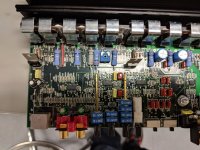
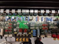
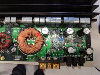
Here are the pictures I have. Like I said, not very interesting as they are more or less drop in parts.
Attachments
-
 IMG_20180620_185854 (Large).jpg378.6 KB · Views: 270
 -
 IMG_20180620_185443 (Large).jpg442.9 KB · Views: 278
 -
 IMG_20180620_185446 (Large).jpg504.2 KB · Views: 246
 -
 IMG_20180620_185451 (Large).jpg443.9 KB · Views: 273
 -
 IMG_20180620_185744 (Large).jpg357.5 KB · Views: 307
 -
 IMG_20180620_185746 (Large).jpg424.1 KB · Views: 162
 -
 IMG_20180620_185747 (Large).jpg416.1 KB · Views: 139
 -
 IMG_20180620_185803 (Large).jpg441.8 KB · Views: 148
 -
 IMG_20180620_185846 (Large).jpg386.5 KB · Views: 208
 -
 IMG_20180620_185816 (Large).jpg474.2 KB · Views: 181

Zapco upgrade
I saw the upgrade you did on your Zapco and was wondering if you would like to make some cash and do the same to mine. I have the same model as yours and it could use some TLC for the long haul. Obviously I would pay shipping both ways and insure it.
Thanks in advance
-Scott
I saw the upgrade you did on your Zapco and was wondering if you would like to make some cash and do the same to mine. I have the same model as yours and it could use some TLC for the long haul. Obviously I would pay shipping both ways and insure it.
Thanks in advance
-Scott
- Status
- This old topic is closed. If you want to reopen this topic, contact a moderator using the "Report Post" button.
- Home
- General Interest
- Car Audio
- Zapco AG750 Rebuild/Upgrade