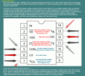
The drivers will have voltages that correspond to the outputs if you read voltage. For driver ICs, you typically have to check the three terminals that are used for the high and low drive to see if any read low resistance.
The attached is for a different IC but gives you an idea of the readings that you'll expect to see.
The attached is for a different IC but gives you an idea of the readings that you'll expect to see.
Attachments
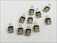
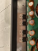
All 4 IRFB5615 output fets are out, and the holes are cleaned up. Took me some time to figure out a good process between heat, tips and the original solder.
Legs 2 and 3 have a resistance of 0.3 ohm, and the multimeter also indicates continutity between those legs, on all 4 fets.
Has anyone ever confirmed: Driver Chip IRS20965S is a suitable substitute for the 98-1036TR (lead free) ? (FYI, the PDX-F4 uses the IRS20965S for its output drivers) .
The PDX-M6 has 98-1036TR listed as the chip, but PACPARTs doesn't list a 98-1036TR as an option for the PDX...however they have it for the MRV series. No big deal on that, but whats annoying is that this chip is a $25 per chip. The readily-available IRS20965 is only about $4 a chip from various vendors.
Last edited:
Surgery didn't go so well. The speaker terminal now outputs -42.5 VDC (orientation of the speaker-connector plug into the amp doesn't matter). I suspect I cooked one or some of the FETs with too much heat, since they definitively fail the FET test in-circuit. The joints all look good and shiny, no bridging, and have better fill than before. But I probably should have used 63/37 thin rosin core solder instead of the 60/40.
I also tested the output driver ICs on-board, and observed low-resistances as per the above guidance. The terminal voltages also were not 99% correct as per service manaul, so the driver ICs also need replaced.
At this point, I'm sending the amp in for repair (the repair isn't that expensive and this amp is easy-to-ship). This is still a very very good amp/board, and I just want it to work again.
It's virtually impossible to heat the FETs too much when soldering the leads. To get a reliable bond to the MEHSA insulators in a Rockford amp, you have to tin the backs of the transistors. You can do this with a 650F soldering iron and not damage the FETs. This applies FAR more heat to the FETs than soldering the leads.
Attachments
I had my iron set to 680 just to get the fresh solder to melt. 650 would get it to melt with over a 1 second dwell time, which is too long. Any lower temperature, and there simply wasn't any melting.
The failure mode also is hard to repeat, on a bench, without using a high current source like the battery. In vehicle, I can feel the alternator and vehicle accessories surge when this amp starts up. On the bench, the power supply I'm using starts to surge, but the amp then clamps itself to 1-2 amps once the power supply reaches its 6 amp limit. I don't have a spare battery to use on the bench.
The failure mode also is hard to repeat, on a bench, without using a high current source like the battery. In vehicle, I can feel the alternator and vehicle accessories surge when this amp starts up. On the bench, the power supply I'm using starts to surge, but the amp then clamps itself to 1-2 amps once the power supply reaches its 6 amp limit. I don't have a spare battery to use on the bench.
The 650 that I referred to was when tinning the backs of the transistors. I typically had my iron set to 850F and never damaged anything soldering the legs. The temperature on the leads drops very quickly as it is conducted through the leads. 680F did no harm.
A lot of amps have an inrush current that will cause the lights in a car to dim when the amp powers up. That doesn't generally indicate that there is a problem. If the FETs are failing, you need to look at the drive signal on the scope to see if it's as it should be.
A lot of amps have an inrush current that will cause the lights in a car to dim when the amp powers up. That doesn't generally indicate that there is a problem. If the FETs are failing, you need to look at the drive signal on the scope to see if it's as it should be.
Hi Mbrogz3000, According to my notes the driver for this amp is not the IRS20965, but the IRS20956S.
I successfully repaired a PDX-M6 using this source IRS20956S International Rectifier,SOP-16,08+PB | IC Chips | UTSOURCE
All the best with your repair.
I successfully repaired a PDX-M6 using this source IRS20956S International Rectifier,SOP-16,08+PB | IC Chips | UTSOURCE
All the best with your repair.
Albert and Perry's comments from earlier are appreciated!
New IR20956S output ICs (from UTSource) are going in tonight, using hot air and fresh solder paste (after cleanup of course). I'll cleanly test the old Abletec IC's as per Perry's guidance, once they are off the board. I'll try post a picture of my work if successful.
Alpine's 'authorized repair facility' (not mentioning the name here, but my review will be posted to Google and Yelp) after telling me they were willing to evaluate and repair the PDX Gen 2 series, then after receipt and eval, eventually ended up determining the parts required for repair are now unavailable, ie. obsolete. (as an authorized electronics repairer, wouldn't they keep track of common failure modes for each product and 'know' whether the parts required for a common repair are obsolete??--different conversion altogether) They said Alpine does not let them substitute other suitable parts, which I can't believe. The only hint given to me by the customer-rep on what needed repaired was that new a 'output driver component' was needed - he would not give me the bill of materials requiring potential replacement. No bench fee, but I wasted $30 in shipping and about a month. After this little experience, I'm building up my own electronics repair bench at home.
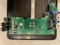
Success! Installed 2 new IRS20956S driver ICs and with the new IRFB5615 output FETS that I installed a month ago, the amp came back to life! Bass definitely sounds stronger than ever before.
Use hot air to remove the old ICs (they were glued on during pic n place), but not to install the new ones - I killed one in the process. Just carefully solder each pad. I'm getting another 11 IRS20956S for safe keeping. Thank you again to Perry and Albert!
Use hot air to remove the old ICs (they were glued on during pic n place), but not to install the new ones - I killed one in the process. Just carefully solder each pad. I'm getting another 11 IRS20956S for safe keeping. Thank you again to Perry and Albert!
Attachments
Last edited:
Hi,
So In conclusion , Is the problem of dc offset created from faulty IRS20956S driver?
I’ve a pdx1000 with same problem . It was working fine than a day start to bumping at turn on ( just at turn on, when I played music it worked fine ) unfortunately I don’t have the possibility to turn off immediately the system because is a factory head unit with a dsp With auto turn on ,so a day it broke my sub (audio development vipera f8). I didn’t measure but I supposed dc offset problem .
Please don't post in a repair thread that was started by someone else unless you are trying to help them.
Start a new thread if you need help with a repair of your own.
Thanks !! I’m sorry
New (or same) problem with this same amp- after about 3 weeks of reasonable use, I started getting scraping noise coming through the sub, along with a lesser DC offset (speaker didn’t pop out as much)- and I could hear some music when signal is supplied. Immediately powered it off to prevent damages.
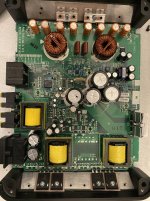
On the bench and opened (but I didn’t have signal-in/gain/bass knob board connected), I have it powered by an old 12VDC Xbox 360 supply capable of 14A. The speaker output measured about -20 V DC, and some AC as well which explains the noise. As I had it powered at idle, the output FETs were getting warm, and one of the two Myler film capacitors started to burst open and smoke. I immediately cut power.
I ended up removing the output FETs and found two of four fail the diode test. With the output FETs removed, the film capacitor isn’t warming up or bursting anymore.
With the FETs removed, I checked the driver IC’s against the service manual and the terminal voltages check ok for the most part, but are not exact, I’m assuming because I’m not using a 14.4V source. I spot checked a bunch of resistors in circuit where the failure is and they all seem to be ok. Nothing looked bad aside from the film capacitor
I don’t know whether I should get another set of FETs to replace along with the film capacitors. What else can I be checking for?..I don’t have access to a scope right now. What also doesn’t make sense is the service manual says that these Film Capacitors are 2.2 uF capacitors both in the schematic and parts list, but the actual part from the board is marked with 105J250A (made by Elecsound) which is 1.05 uF (and the undamaged one measures 1 uF by a basic multimeter). If I get new Film Capacitors, should I get 2.2 uF or 1.05 uF ? Any ideas why it’s failing this way now?
Last edited:
The 105 isn't 1.05uf. It's 10 and 5 more zeros in picofarads. 1,000,000 picofarads is 1uf.
The caps are likely failing because too much of the carrier is passing through the inductors. This could be due to the amp operating far off the normal carrier frequency or due to defective inductors.
The caps are likely failing because too much of the carrier is passing through the inductors. This could be due to the amp operating far off the normal carrier frequency or due to defective inductors.
Hi Mbrogz3000,
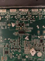
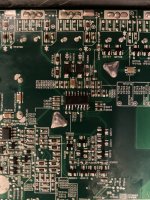
I also noted this discrepancy between the Service Manual and the actual components used. On the amp that I repaired C4003 and C4004 also failed, see attached picture. I cannot find the more detailed picture of the capacitors that I removed.
I used ECWF2W105JA as replacements, and have not had a return complaint on that amplifier.
If only one capacitor failed, see if the rail to rail switching frequency is the same between the two drivers, when you get access to scope again.
All the best!
Attachments
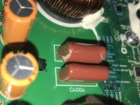
Thank you Perry and Albert - Albert's picture is how my C4003 failed. C4004, off the board, still measures 1 uF. I ultimately was going to purchase the same rated part (pair) that was removed, but ended up going down the rabbit hole of various sound forum debates over Polyester vs. Polypropylene film, as well as dealing with physical size considerations. That Panasonic was on my potential list, and I may just get go with if this is still worth while to repair. C4002 and C4005 measured their rated capacitance on board.
Is there a better way to test the inductors aside from measuring resistance while on-board? (I don't have an inductance meter.) Unfortunately they both are measuring 0.5 ohm. The inductors are not burnt looking, although they did get warm when this unexpectedly happened.
Is there a better way to test the inductors aside from measuring resistance while on-board? (I don't have an inductance meter.) Unfortunately they both are measuring 0.5 ohm. The inductors are not burnt looking, although they did get warm when this unexpectedly happened.
- Home
- General Interest
- Car Audio
- Alpine PDX M6 - 43VDC Output