The amp originally had some of the outputs fail due to one of the insulators between the FET's and the heat sink become conductive and short to the heat sink. There were a few SMD transistors failed as well. Someone had also changed only one power supply FET. I changed them all as to have matching date codes. I replaced all the outputs as well. Nothing seems to be getting hot just can't pin point the current draw.
It does produce clean audio.
It does produce clean audio.
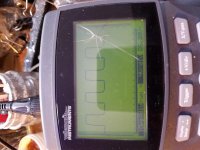
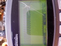
I apologize for the pic quality. My big scope is down had to use the hand held.
It looks like one supply is idle and the other is at higher duty cycle?
The scope is in auto range not sure why one reading was in "ms" and the other "us".
It looks like one supply is idle and the other is at higher duty cycle?
The scope is in auto range not sure why one reading was in "ms" and the other "us".
Attachments
Just dug this amp back out. Its my amplifier and I wasn't in a hurry to repair it. I'm caught up and want to get back to it.
The rail and regulated are slightly different. I'm not sure if this is causing the current draw. Something is pulling the + rail down.
Rail voltage is +65vdc and -81vdc
Regulated is +13vdc /-17vdc
The rail and regulated are slightly different. I'm not sure if this is causing the current draw. Something is pulling the + rail down.
Rail voltage is +65vdc and -81vdc
Regulated is +13vdc /-17vdc
I also found at TP1000 R6 and R1022 should have -19.50vdc and they have -27.50vdc.
Also found that the only regulator in the output section with proper readings is Q2000. Q2000 has -27vdc in and -6.5vdc out.
Q2010 and Q2012 have only 13.71vdc in which is low and 11.5vdc out which is normal.
Q2001 has 13.71vdc in and only 6.5vdc out.
Could this Q2001 MJD44H11 be pulling the others down and causing excessive load on the regulator and rectifier?
The rails for the outputs aren't referenced to anything and there is no positive or negative rail.
The regulated rails are referenced to the RCA shields. What is the regulated voltage (the +13vdc /-17vdc) with the black probe on the RCA shields?
I just posted what my meter was reading on the screen for the rectifiers but I was referencing from input ground terminal.
Regulated if I use the input rca shield the voltages keep going down and down. I can wait till they settle and give you those readings?
If I use the pass thru shield I get steady readings as follows:
U1000
27.42
13.70
12.39
U1001
-17.03
-27.35
-15.28
Sorry I should have posted the readings with each leg posted with it. I could have got off on the configuration.
The amp produces clean audio and seems to work well just drawing 8 amp of current at idle and I know this is not normal. One would think if there was a problem on the audio side the amp wouldn't function properly.
The waveforms on the drive circuit for the power supply look good, I'm just unsure why the current draw.
- Status
- This old topic is closed. If you want to reopen this topic, contact a moderator using the "Report Post" button.
- Home
- General Interest
- Car Audio
- Rockford Fosgate T2500-1bdcp