Got this amplifier with blown PS fets.
Before installing new fets, i scoped drive signal - which was good.
Installed new fets, new drivers and amplifier now is drawing excessive current.
I removed rectifier from board to isolate output section - no luck.
Could be SG3525 bad? Which shows only under load, because before drive signals were good.
Audison SRX1
big quote!!Check Gate resistors and pullup resistors,and also diodes used for the gates

I forgot, if you have one or more defective gate resistors, the MOSFET load may not be the same for everyone, and worse, if the gate resistors are interrupted, the power supply may not work well and MOSFET would heat up very quickly, absorbing a large amount of current from your main power supply.
![41F4bhNyyLL._SX355_[1].jpg](/community/data/attachments/600/600279-bbd734f8a9e727c73239a34de294ffd7.jpg)
I asked you for a picture of the SRX1 because there are two types, the first one having the blue heatsink and the second type that is black
I never happened to have the trsf shortcut
If, without the power rectifier, the current is very high, try to figure out if there is any component on the pcb (not the fets) that heat up a lot or if the wires of the trsf get very warm. Also try to see if there are any burnt track
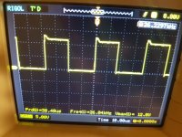
I know it's difficult but if you can, post 2 picture of the Drain mosfet waveform, on both side of trsf, after turning-on the amplifier (before making any damage, even if it drawing high current, just for 1 sec)
I never happened to have the trsf shortcut
If, without the power rectifier, the current is very high, try to figure out if there is any component on the pcb (not the fets) that heat up a lot or if the wires of the trsf get very warm. Also try to see if there are any burnt track
I know it's difficult but if you can, post 2 picture of the Drain mosfet waveform, on both side of trsf, after turning-on the amplifier (before making any damage, even if it drawing high current, just for 1 sec)
make sure if the squarewave is present and identical on ALL gate pad.Well, I will try it later.
Also i tried to load transformer with few fets.
I dont know how to explain easier, but when there is installed only 2 fets - it works OK, draws about 400mA. Current increases as I install more fets.
if it is, then, you have counterfeit fets.It is, all fets have drive signal as shown before.
it's also possible that your 3525 is defect, but very unlikely.
can you make a photo of top and bottom of the board in trf/fets area?Doubt it, originals were bought from Farnell.
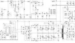
There is nothing else to add.I hope this schematic may be usefull
If the amplifier absorbs the right amount of current by installing only 2 MOSFETs (1 per bank) the problem may depend on faulty MOSFETs, MOSFETs too different from each other, pull down resistors or damaged gate resistors, damaged drivers or at maximum sg3525 does not work well (but it is unlikely).
If the scheme you have published is identical to your amplifier, with 10ohm gate resistors it is easy to encounter resistors that seemingly appear to be in the standard but which are actually damaged.
Also the driver stage could work well with a small load (1 MOSFET per bank) and cause problems when loading more (all MOSFETs installed).
In addition, R9 and R20 may look intact, but better controllable.
At the end of all these controls, if you still can not find the problem, try changing sg3525.
Make this tests always without rectifier.
Also D12 & D9 from the secondary winding must be removed during this test.
- Status
- This old topic is closed. If you want to reopen this topic, contact a moderator using the "Report Post" button.
- Home
- General Interest
- Car Audio
- Audison SRX