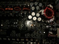
Unfortunately I can not see very well.ian, is R769 4,72k?
I do not have an electric diagram to consult.
It seems to me that R769 is equal to R763 (10K), I say it because it seems to be connected to ZD701 and ZD702 respectively.
is a typical resistor + zener configuration, probably to stabilize a lower voltage.
Anyway, I seem to understand that this area is related to the power supply.
Your power supply works fine, so it makes no sense to go looking for something at that point.
Remember, you have a missing trimmer.
It may be useful to adjust the switching frequency fine (in relation to that channel).
If you can understand the value of the other trimmers, you can install a trimmer of the same value in the space where it is now missing.
As you solve the VCC problem, you need to be very careful, as that trimmer will need to be adjusted very well for the same switching frequency of the other channels.
ian, is R769 4,72k?
Amp gone already.
There is no port in that location.
Attachments
Last edited:
Thank you ian , for the information.
I have continued to investigate and I have found, that at the exit of L7905, 14V are obtained ... they should be -5v, right?
what is your reference point measuring this?
That's not right!the reference point is the central pin of L7905
the central pin can be used as a reference only for positive voltage regulators.
L7905 is a negative voltage regulator, and the reference point must be taken to the first pin because its configuration is different from the positive regulators.
POSITIVE REGULATORS:
1. in 2. gnd 3. out
NEGATIVE REGULATORS:
1. gnd 2. in 3 out
Ooops!
I had not fallen in that detail! I thought the configuration was the same for the 78xx and the 79xx
I'm sorry I screwed up
Anyway, I've noticed a small difference ..
When I do the voltage measurements, the power LED turns into the two colors red / blue, and yesterday when I removed the L7905 to check it, a light bulb lit on my head and I connected the amplifier without this piece, then the power LED it became only blue ...
I think I have to keep track of this path ...
I have ordered these regulators to send me ..
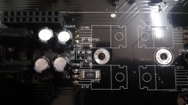
you must have 12/15v at this point.7905 have been replaced by new ones.
In pin 10 of IRS2092S I have -26.83v measured with black tip in -B and red tip in pin 10.
Check VCC regulator!
The negative voltage that you have measured is because the vcc is obtained from negative rail.
7905 and 7805 are probably used to generate VAA and VSS that are respectively +5v and -5v.
of courseVCC regulator 7812 measured with black tip in B- are:
in: -11,4
ground: -26,7
out: -14.5
Now, measured with black tester tip in ground of the regulator I have:
in: 15.29v
out: 12,23v
I think this regulator is in perfect condition
At last!
You were right, Mario
I replaced all the IRS2092 ICs and managed to see square waveform in my scope on all the gate pins of the output fet.
I tried the amplifier with audio, and perfect sound on all channels.
I do not know why my head did not understand that these IC'S could be in bad condition, I also thought it strange that the four had failed, but it was like that.
Thanks MarioRestucci for your help.
Big!!
Sorry if this is an old post or if this has been answered but I was wondering where you were able to find these or if there's an equivalent? Thanks for any help,At last!
You were right, Mario
I replaced all the IRS2092 ICs and managed to see square waveform in my scope on all the gate pins of the output fet.
I tried the amplifier with audio, and perfect sound on all channels.
I do not know why my head did not understand that these IC'S could be in bad condition, I also thought it strange that the four had failed, but it was like that.
Thanks MarioRestucci for your help.
Big!!
- Home
- General Interest
- Car Audio
- Rockford Fosgate M400-4D