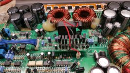
Hey folks, after finishing up the DLM4500 I decided to try my hand at the Asian class D clone driver board. You know, the one that always toasts Q124/125. I am going to be reverse engineering it, getting a working schematic, probably do the stock board layout and then hopefully work on making it more robust. I have been talking with Perry about this via email off and on for a while now, and he had some good ideas for some improvements, so I am going to take a shot at it.
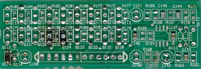
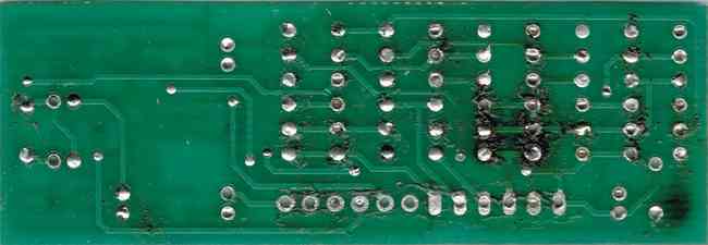
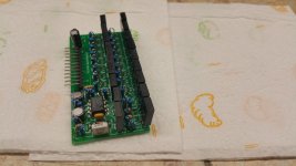
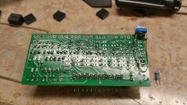
Below are some pics of a stripped driver board that I scanned to work with while I am ringing it out. High resolution images will be linked below the low_res version. I will also link the BOM spreadsheet that I started. I need some help here. On my board D112 and D113 had no legible markings on the case. I think they are just normal switching diodes, probably 1N4148, but would be nice to have confirmation. Also, C143-C148 are all SMD ceramics on my board. After my debacle with the DLM caps I chose not to remove these yet to attempt to measure. I ordered a good capacitance meter, and had expected it to be here by now, but it still has not arrived. I know some versions of this board used poly through hole caps in these locations, if anyone can fill in the missing values that would be awesome.
I'll start drawing schematics tonight and hopefully have an update before morning")
Front, High Resolution
Back, High Resolution
BOM in ODS format
Thanks,
Jason
Below are some pics of a stripped driver board that I scanned to work with while I am ringing it out. High resolution images will be linked below the low_res version. I will also link the BOM spreadsheet that I started. I need some help here. On my board D112 and D113 had no legible markings on the case. I think they are just normal switching diodes, probably 1N4148, but would be nice to have confirmation. Also, C143-C148 are all SMD ceramics on my board. After my debacle with the DLM caps I chose not to remove these yet to attempt to measure. I ordered a good capacitance meter, and had expected it to be here by now, but it still has not arrived. I know some versions of this board used poly through hole caps in these locations, if anyone can fill in the missing values that would be awesome.
I'll start drawing schematics tonight and hopefully have an update before morning
Front, High Resolution
Back, High Resolution
BOM in ODS format
Thanks,
Jason
Schematic is done, may have errors, I will have a better idea of how accurate it is once I do board layout.
Click for PDF
Thanks,
Jason
Click for PDF
Thanks,
Jason
Hey folks, I'm going to work on board layout tonight and hopefully make another revision of the schematics with some of the improvements Perry and I spoke about.
Question for Perry, you mentioned in one email that it would be nice to have the constant current source adjustable. If I am on the right track, LMK. I am thinking dropping R175 down to 330R and adding a 1K pot in series. By my calculation this gives the current source range at 3.8-15 mA. That is probably more than is needed on the high end, but I think it will be okay.
I'm going to look into options for replacing the final driver transistors too as well as seeing if I can find a good replacement for KTC/2SC1027 and KTA/2SA1023 transistors. This complimentary pair does not seem readily available anymore. It seems many Asian manufacturers have them still, but not a lot of luck with US vendors.
Thanks!
Jason
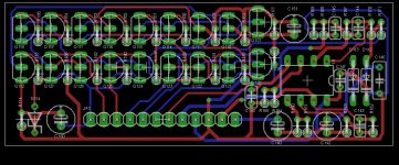
Ok, I just finished up the stock layout, I laid it out with all through-hole parts for ease of assembly for DIYers. In order to fit the same footprint as the stock ones the resistors had to be mounted vertical and thing are really tight. I am going to work on a new version next and I am probably going to add a little height to the board. I know that the ones I have had in my possession had a little headroom. Most of them have had room for more width too, but I think all probably have a little wiggle room on height.
Attachments
Thanks Perry, I figured I would start with those, I use them as pre-drivers in other amps, so I have a good stock of them.
The MPSA42 is rated for significantly higher voltage though. I am not sure I understand exactly why they went with this transistor, especially since the other half of the pair is rated for far less voltage and the MPSA92 seems to be the appropriate compliment for a MPSA42.
So, the next question is how much current does the output driver actually need to source/sink. I'm wondering if the KSAS1381/KSC3503 might be a more appropriate pair for the final driver stage. They are rated for the same voltage as the MPSA42, they are almost twice as fast, but they are only capable of 100mA collector current. Ultimately the load they are driving is the gates on a whole mess of FETs, I can't see how that could require the ~1 amp that a parallel pair of MPSA42's are theoretically capable of.
Can anyone help clear up why these initial design choices may have been made? I would really like to better understand the logic rather than just trial and error my way toward a working replacement.
Thanks,
Jason
Current ratings for DC and high frequency circuits is very different. There are losses in higher frequency circuits that make the transistors operate at higher temperatures. This is probably why the boards that use the large transistors still run so hot. The operating temperature determines the current rating.
The A42/92 are rated for 150v. The 1220A/2690A are rated for 160v.
The A42/92 are rated for 150v. The 1220A/2690A are rated for 160v.
Okay, that makes more sense. For some reason I thought the A42/92 were rated for 300V maximum. I'm not going to have time to redesign tonight, but I'm thinking ultimately it would be neat to design a board that could use either type of transistor. Without drawing it up, I am not sure how realistic that is since the A56/42/92 have a different lead order than the KSA/KSC parts.
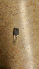
I love the idea of being able to heat sink these things and change their orientation though, I think like you mentioned, this will go a long ways toward improving reliability. Worst case scenario if the KSA/KSC parts don't make good replacements, then I will find room to double the existing driver transistors and maybe even see about thermal bonding adhesive and heat sinks for the TO-92 parts. Surely someone has made a thermal solution for this in the past.
Thanks,
Jason
I finished the schematic for a driver board that will allow either TO-92 or TO-126 cased transistors. I managed to route the board, but I was out of time so I didn't get to export the schematics or the layout. The layout should allow for heatsink on the TO-126 transistors and I think overall I ended up having to make the board .25" taller. In the end, as long as the KSA1220A/KSC2690A are a good fit for the project, then I can re-do the layout to remove all the TO-92 devices.
I'll post up more tomorrow. Gotta wrap things up he for now.
Thanks,
Jason
I'll post up more tomorrow. Gotta wrap things up he for now.
Thanks,
Jason
As promised here is last nights work. As a side note, the schematic should be a lot more visible now, I figured out how to export in in black&white instead of eagle's stock colors. A little explanation on the schematic, there is now a parallel transistor with a "A" suffix on it's part number. The A suffix parts are to designate the alternate and hopefully upgraded transistors. In the final board only the original or the "A" part will be populated.
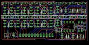
The attached screenshot is the board layout for a modified driver. The board ended up having to be about .3" taller. I think I could get it back down to the stock footprint if I used SMD, but I also think this will fit in the majority of amps. The KSA1220A/KSC2690A will be in horizontal rows on the board, basically perpendicular to the original TO-92 parts. With the TO-92 locations unpopulated, there should be room to heat sink the transistors and hopefully increase reliability. I think I am going to submit the design to oshpark tonight, I'll probably start with the minimum order until I am sure the upgraded parts will work.
Link to the schematic clicky
Let me know if you spot any errors!
Thanks,
Jason
Attachments
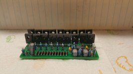
I had to backburner this project for a little while. Funds were kind of tight and I really wanted to do some testing to see if the transistor upgrade was feasible. I found some time to tinker with it this weekend. I did some creative lead bending and got the upgraded transistors in the stock board. I couldn't find and right angle headers in my stash either, so I put a socket in the amp and used a normal header. It gets it up high enough to mount it but I'll order the right headers if this works out.
I had to go inside and make the kids lunch. I powered it up real quickly and it powers up, no protect and didn't instantly smoke a bunch of transistors. I'll do some audio tests in a bit and see how it runs.
I had to go inside and make the kids lunch. I powered it up real quickly and it powers up, no protect and didn't instantly smoke a bunch of transistors. I'll do some audio tests in a bit and see how it runs.
Attachments
And it works. Had a bit of issue at first, no audio whatsoever out of it. I thought maybe I had a bad solder joint, I went back over the whole board and did not find an issue. I fired up the scope and found I had rails and 15v rails, the mute was working correctly but zero gate drive...
I went over the transistors one by one to make sure I didn't mix up a pair, they all looked right. Then I started using my schematic to check the smd resistors I replaced. I wanted to make sure I got all of them soldered down good and no shorts. When I got to the current source resistor I knew immediately what I did wrong. I repopulated the board based on my bom spreadsheet I had made. On my schematic I had 910R down for the resistor, in my bom I had 910K. I really had to dig to find a 910K resistor yesterday, so when I saw 910R I knew instantly where I screwed up...
Anyhow, no 910R in stock so I used 1k for now. It's working and seems fine, but I might have a 890R somewhere and I may swap it out to see what the higher drive current does for it.
The output drive pairs still get pretty dang hot, however with my "universal" board design a tech should be able to heat sink them as well and that will help a bunch.
Thanks for watching!
Later,
Jason
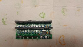
So, I have had a few minutes to go back to this project. I populated one of my upgraded driver boards with all KSA1220A/KSC2690A transistors and I am having some odd results. With all 1220/2690 in place, the amp will power up and produce audio while on a 1R current limiter. With no current limiter in place the amp draws about 20a and still produces audio, but obviously something is very wrong. Q116/117 are the only transistors that get hot. I swapped out the transistors in the long tailed pair, the constant current source, and what I would call buffer or pre-drivers back to MPSA92 for the buffers and KSC2316/KSA916 pairs in place of what would have been 2SC1027/2SA1023's in the factory design. After these changes, my old soundstream PIC17000.1D runs fine with this card. I figured that the bigger transistors must have been a bit to hard to drive.
I was still happy with these results until I popped the card into my newer powerbass 1500.1. Even with the smaller buffers this amp draws 20a and Q116/117 get hot. I have been over the factory card from this amp with a fine tooth comb. The only difference is that the PB card uses 2N5401 in place of MPSA92's and 2N5401/5551 in the long tailed pair, but 2SD600K for the current source and 2SB631K for the muting transistor.
The 2N5401/5551 are good for a bit higher frequency than the MPSA92 according to their datasheet, but I cannot see why that would matter. I am at a loss as to why this works in one amp and not the other. The rails in he SS amp are +/-70V vs +/-60V in the PB. Other than that, they use the same gate pulldowns and the same value gate resistors between the two amps. I actually think they use the same outputs and number of outputs, but I wouldn't swear to that yet.
One other oddity, the stock PB driver does work in the older SS amp, but even the stock SS driver does not work in the PB amp.
Any thoughts or suggestions?
Thanks,
Jason
Attachments
I'll give it a shot Perry. I figured it might be due to the constant current source since it would run pretty good on a current limited supply. That was actually my first thought when the card initially didn't work in the SS amp, but when I got that one going by swapping out the above mentioned transistors I disregarded it.
I'm starting to wish I had designed this with an adjustable current source to begin with. If it turns out to be needed often I'll look at putting a trimmer on the boards.
Thanks!
Jason
I'm starting to wish I had designed this with an adjustable current source to begin with. If it turns out to be needed often I'll look at putting a trimmer on the boards.
Thanks!
Jason
You nailed the issue on the first try as usual. I bodged in a 2k trimmer and adjusted until I had an idle current of about 2.5 a. In the end we landed on a value of 1K75 for the current source resistor.
So now, the question is, should I try again using all 1220/2690 parts? I think that currently I have it working with them in the locations that are typically a problem and in need of an upgrade. My gut says call it good, and run a few with the current design and see how they hold up.
My other question is, how much variation is there between amps. Is this something that needs a trimmer to adjust current, or should I just leave the current source unpopulated and allow the downstream techs to determine their own value? I can redesign the board without to much trouble.
I only have one more amp of this general design to test cards in, a old planet audio big bang "3kW". I'm leary of offering these cards with a fixed current source of this is going to be a big compatability issue.
Thanks,
Jason
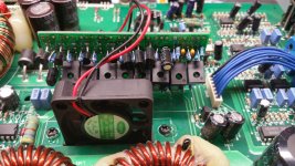
The photo shows all 1220/2690 parts. Are you using something else?
For this version, maybe include the 2k pot wired in but only for use to find the correct value.
Are you referring to the BB2400 and similar that use the large outputs?
I'd be interested to know if these transistors work better than the TO-220 transistors. At least with your design, you can add a piece of aluminum stock as a heatsink/spreader.
With a piece of 1/8" aluminum stock and some 3mm of #4 screws, will this board fit in the same space as the old boards?
I mentioned earlier that at first with the 1220/2690 in the upper row as shown in the pictures, the SS amp was having high current issues too. I swapped out all the transistors except the final driver transistors with their stock parts or a good sub. I used mpsa92 for the buffer or pre-drivers and I used KSC2316/KSA916 in place of 1023/1027 pairs everywhere else. This got the SoundStream running with no abnormal current draw, but it didn't work in the powerbass. In the design I allowed for both transistors footprints and pin order just in case I had to mix and match. I think I'll build one more with all 1220/2690s and adjustable ccs. So far they do seem to stay cooler, even with no heat spreader.
I'll try to get some pictures of what I finally ended up with in the next few days. I'll keep you all posted. Thank you for the advice!
*edit* to clarify, the bottom row is still 1220/2690 except for the current source transistor.
*edit again, found a pic
Jason
I'll try to get some pictures of what I finally ended up with in the next few days. I'll keep you all posted. Thank you for the advice!
*edit* to clarify, the bottom row is still 1220/2690 except for the current source transistor.
*edit again, found a pic
Jason
Attachments
Last edited:
- Status
- This old topic is closed. If you want to reopen this topic, contact a moderator using the "Report Post" button.
- Home
- General Interest
- Car Audio
- Generic Asian Clone driver board RE and Clone