hello
i'm trying to make a smps (for car amp) and i cant find the right toroid . i got old pc power supplies (2 of them) and i wanna know if its possible to use the toroids that filters the +5V output of an old pc supply for that porpuse or maybe its too small ??
and if it is possible (i got 2 toroids) what will be (aprox) the output power?
sss said:i'm trying to make a smps (for car amp) and i cant find the right toroid . i got old pc power supplies (2 of them) and i wanna know if its possible to use the toroids that filters the +5V output of an old pc supply for that porpuse or maybe its too small ??
I suspect these cores are used for differential filters and in that case most likely mpp or other powder based cores and not ferrites. Assuming you want to use these for the push-pull transformer in a DC to DC converter they are not what you want. If the cores are used for common mode filters then they probably are ferrites and might work. A differential choke is usually identified by having one winding and a common mode choke will have two windings. If these inductors are used for a buck regulator, they will likely be a powder based core and not a ferrite.
Study the free literature at the following website: http://www.mag-inc.com/
They have good application notes on ferrites, powder cores, etc. You should find tables, charts, and equations to help you easily choose the correct core types and sizes, and design transformers and inductors for your power supplies.
These yellow-white tororid cores found in AT and ATX power supplies are made of iron-powder materials and are only usable as energy-storage inductors in buck or boost regulated topologies
They are not usable as transformers due to its low permeability and its resistive nature that causes high losses in the core when used as a transformer
As a transformer, you should use the big EI or EE power ferrite cores present on all these power supplies
With a transformer and an inductor of that characteristics you may easily build a transformer coupled buck converter of up to 500W. This is nothing but the topology used on nearly all AT and ATX power supplies
What is wrong with using ferrite toroids for transformers? I understand there may be more labor involved in winding them, especially when a high number of turns are required. They have a low profile and good inherent shielding properties. No gap is needed for current mode PWM operation. Leakage inductance using a toroid can be an issue depending on the core shape and number of winding turns. Some trade-offs.
There is nothing wrong in using ferrite toroids as transformers, but iron-powder cores are not suitable as transformers
Leakage inductance with ferrite toroid transformers is about the same obtained with EI or EE standard cores, provided the same core materials and sandwitching winding techniques are used, but it's almost imposible to get perfect sandwitching in a toroidal core so coupling tends to be worse
In the other hand, standard AT and ATX PC power supplies doesn't contain any ferrite toroid big enough to be used for a car-audio SMPS, they contain only a big iron-powder toroid. Only the main EE or EI core is usable as a power transformer
Eva said:Leakage inductance with ferrite toroid transformers is about the same obtained with EI or EE standard cores, provided the same core materials and sandwitching winding techniques are used, but it's almost imposible to get perfect sandwitching in a toroidal core so coupling tends to be worse
Do not fully agree with that. Toriods can be covered fully by windings, greatly reducing leakage. Also the length of the winding can be larger what means fewer layers. Fewer layers reduce proximity effect, but interleaving does indeed as well. Also they have a larger radiation surface for the copper what helps cooling. Have used 36mm F4 material toroids to make PP 12V up-converters of around 100W that hardly needs a snubber.
Cheers
")
I was once a fan of toroid transformers, then found out the crude reality...
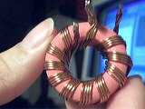
Look at these two transformers :
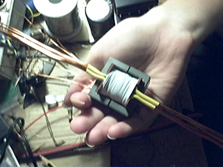
Both are intended to reduce 200V DC to 14.4V DC
The toroid [36mm OD] is designed to operate at 50Khz while the EE [42mm L] is designed to oprate at 30Khz
The toroid has two 4 turn external secondaries and a 48 turn internal primary. The EE has two 5 turn secondaries, one layer each, sandwitched by two 30 turn primaries, one layer each, in series [one internal and one external]
The toroid has about 20uH leakage inductance while the EE has about 10uH, in both cases seen from the primary with shorted secondaries
Notice that the sandwitched EE by far outperforms the toroid in leakage inductance even though it's designed to operate at a lower frequency
In favour of the toroid, I have to say that it's not a power material but a Ferroxcube 3E-25 high-permeability signal ferrite while the EE appears to be a low permeability power material [unknown make/model/material]
Anyway, I think I wouln't get less than 10uH leakage inductance by using a low permeability material in the toroid, since the only difference would be that the power material could be used down to 30Khz with the same turn counts and without saturation [and it may be posible to reduce turn count to 3 and 36, but not further]. Leakage inductance depends only on the windings, not on the core material
I have not tried sandwitching in the toroid since It's almost impossible to get it right since each layer has to fill the entire winding area and the toroid has different internal and external winding areas [you get better coupling in the outer side at the expense of worse coupling in the inner side and vice-versa]
Look at these two transformers :
An externally hosted image should be here but it was not working when we last tested it.
Both are intended to reduce 200V DC to 14.4V DC
The toroid [36mm OD] is designed to operate at 50Khz while the EE [42mm L] is designed to oprate at 30Khz
The toroid has two 4 turn external secondaries and a 48 turn internal primary. The EE has two 5 turn secondaries, one layer each, sandwitched by two 30 turn primaries, one layer each, in series [one internal and one external]
The toroid has about 20uH leakage inductance while the EE has about 10uH, in both cases seen from the primary with shorted secondaries
Notice that the sandwitched EE by far outperforms the toroid in leakage inductance even though it's designed to operate at a lower frequency
In favour of the toroid, I have to say that it's not a power material but a Ferroxcube 3E-25 high-permeability signal ferrite while the EE appears to be a low permeability power material [unknown make/model/material]
Anyway, I think I wouln't get less than 10uH leakage inductance by using a low permeability material in the toroid, since the only difference would be that the power material could be used down to 30Khz with the same turn counts and without saturation [and it may be posible to reduce turn count to 3 and 36, but not further]. Leakage inductance depends only on the windings, not on the core material
I have not tried sandwitching in the toroid since It's almost impossible to get it right since each layer has to fill the entire winding area and the toroid has different internal and external winding areas [you get better coupling in the outer side at the expense of worse coupling in the inner side and vice-versa]
Thanks for the info, Eva. I am gald to read your good ideas after the barbaric indident of last week. Now I am more glad that I purchased a box of surplus E-cores. I have quite a lot of experience experimenting with the 25mm toroids I had purchased a few years ago. Now I hope to compare the performance of the two types using your lucid guidelines.
There are too many turns on that toroid; however, not a good application for a toroid.
If either a toroid or an E-core were the best for all applications then the core manufacturers would only need to make one core type.
A toroid can be good for containing magnetic fields and this is important in the certain applications, such as a 50/60Hz power transformer for an audio amp. Toroid cores work best when the number of primary and secondary turns is the same or a close multiple of each other, such as 2, 3, or 4 to 1. Lowest leakage inductance is obtained when all winding are as close to the core, and as close to each other as possible. Windings physically away from the core or each other cause more leakage. In other words, one layer of windings (primary and secondary) covering the toroid will yield lower leakage. This is difficult and not always practical because of the shorter circumference on the inside of the core. A core with less difference between OD and ID with more height to obtain the same core area will generally yield less leakage. For low leakage don't try to fill up the hole, but instead use a larger toroid.
For SMPS applications with high input voltage and low output voltage, the toroid core is probably a poor choice unless your design can use the leakage inductance for resonant switching. Interleaving windings on toroid cores will reduce leakage somewhat, but is labor intensive and usually not pretty.
A pot core can have very low leakage and great shielding, but poor power handling when copper losses are large, because it holds the heat.
Multiple layers of windings on a core will increase AC resistance of the copper due to skin and proximity effects and can be very troublesome at frequencies above 100 KHz. Interleaving of windings and more than one layer works well at lower switching frequencies where the AC resistance is small.
Planar magnetics have advantages at higher operating frequencies. The magnetic cores can have more cross section area and less winding area. From circuit board to circuit board the leakage will be very close. For a given core area, higher frequencies require fewer turns and with fewer turns leakage is less. Skin and proximity effects are less for thin/wide circuit board runs. High power can be difficult and expensive, requiring more PCB layers with more circuit runs in parallel.
I just have one simple question...How do you tell exactly how much power your toroid is suited for? Or I guess a better question is, how much current handling is it capable of? I know there are many things that effect this, but I am mainly interested in toroid selection (permeability and flux density), and the calculations seem to elude me.
Perhaps rather than asking for a drawn out answer, though I would prefer it, I will post the stats for the toroid I have been looking at, ad someone can tell me what it is capable of (hopefully)...by the way, application is 12V DC-DC converter, would like to make 40V rails, loaded. Planning on a 1:4 ratio to overcome the diode loss, etc.
By the way, I appreciate the help last time, Eva, very knowledgeable!
Perhaps rather than asking for a drawn out answer, though I would prefer it, I will post the stats for the toroid I have been looking at, ad someone can tell me what it is capable of (hopefully)...by the way, application is 12V DC-DC converter, would like to make 40V rails, loaded. Planning on a 1:4 ratio to overcome the diode loss, etc.
An externally hosted image should be here but it was not working when we last tested it.
By the way, I appreciate the help last time, Eva, very knowledgeable!
The power handling will depend on the amount of wire you can get on the toroid. You will need to scale the number of primary turns to get an acceptable flux swing. Np = 10^8*Vin/4*Bp*Ae*f , where Np is the number of primary turns (1/2 of a center-tapped winding), Vin is the input voltage, Bp is the peak flux swing in one direction, Ae is the core effective area, and f is the switching frequency. This assumes you are using a standard push-pull PWM or square wave drive circuit. A good starting value for Bp is about 2000-2500 Gauss.
A long while back I actually used a saturating core inverter to power my car stereo.The key to making it work right was to place an inductor in series with the transformer primary center tap to limit the shoot-through current in the switches when the transformer core saturated. Since the transformer was designed to saturate, it was very small. I don't know what the actual power rating of the supply was, but it generated +/- 28V to drive a discrete power amp of my own design, anfd it could bottom any speaker I put in the rear deck of my car.
A long while back I actually used a saturating core inverter to power my car stereo.The key to making it work right was to place an inductor in series with the transformer primary center tap to limit the shoot-through current in the switches when the transformer core saturated. Since the transformer was designed to saturate, it was very small. I don't know what the actual power rating of the supply was, but it generated +/- 28V to drive a discrete power amp of my own design, anfd it could bottom any speaker I put in the rear deck of my car.
Now is that Np=(10E8*Vin)/(4*Bp*Ae*f ) ? Otherwise the number seems way too large. Ae= effective area, is that a cross section of the toroid, simply the surface area of the entire toroid, in centimeters, meters, millimeters, or some other area? Now that gives me the number of turns to use, I was planning on using 4, since that seems to be the common practice for car SMPS, but it's nice to have the actual calculations! However, how does that relate to power?
ok lets say my primary coil is 4 turns each (center tapped) and
i'm using a toroid
now when winding the primary i need to cover all the surface of the core ,right?
so how should it be ?
4 turns covering the core and then another 4 turns above it ,
or 4 turns covering half the core and another 4 turns covering the other half
thanks
i'm using a toroid
now when winding the primary i need to cover all the surface of the core ,right?
so how should it be ?
4 turns covering the core and then another 4 turns above it ,
or 4 turns covering half the core and another 4 turns covering the other half
thanks
(not that my power Q is resolved, but...) Ok, now I am a little confused. What I am seeing is this, correct ? (primaries are different colors, these examples are 4 turns, center tap, 4 turns)
For some reason, I thought that the primaries had to be as identical as possible, example:
It could be that they're really the same, but the first example covers the area of the toroid much more nicely if you have few windings, by interlacing the primaries rather than sandwiching them into one bundle. I would prefer to do it the first way, especially with thick wires or multiple wires as Eva has shown, I just didn't know that it was close enough to 'identical' windings. Or perhaps since each of your primaries is four wires, you are winding two from one primary with two of the other, then interlacing the other two from each? (It doesn't look like it though, just grasping at straws)
An externally hosted image should be here but it was not working when we last tested it.
For some reason, I thought that the primaries had to be as identical as possible, example:
An externally hosted image should be here but it was not working when we last tested it.
It could be that they're really the same, but the first example covers the area of the toroid much more nicely if you have few windings, by interlacing the primaries rather than sandwiching them into one bundle. I would prefer to do it the first way, especially with thick wires or multiple wires as Eva has shown, I just didn't know that it was close enough to 'identical' windings. Or perhaps since each of your primaries is four wires, you are winding two from one primary with two of the other, then interlacing the other two from each? (It doesn't look like it though, just grasping at straws)
I suggest that you go for a bobin based transformer from Ferroxcube or Siemens. One good example is E32.
If you run at about 70kHz you can do with only two primary turns made out of copper foil (20x0,2mm). Wind the first primary closest to the bobin. Then wind the two secondaries interlieved on one layer. Last wind the second primary.
You will end up with a primary resistance of about 3mohm and really good coupling between the primary and secondaries.
With such few turns you can never design a good toroid transformer because you simply cannot get the coupling that you get with foils. The absolute optimum would be to wind as I described above but with only one primary winding. That way you would have the entire primary voltage "seeing" the secondary winding. This is possible if you increase the frequency to 150kHz or if you increase the core area. If it is absolutely necessary to obtain low building height you can allways remove the pins of the bobin and only use the cylinder in the middle.
Hi Wrenchone,
Thanks for answering that. This also have been in my head for many years. Looking at any magnetic equation, Faraday equation, including the one in mag-inc handbook, I drew conclusion that the limit of power handling of toroidal ferrite is how much wire you can put in them. Nothing to do with Ae or window area. But I dont believe myself for my conclusion.
Your short answer has clarify it. Thank you
The power handling will depend on the amount of wire you can get on the toroid.
Thanks for answering that. This also have been in my head for many years. Looking at any magnetic equation, Faraday equation, including the one in mag-inc handbook, I drew conclusion that the limit of power handling of toroidal ferrite is how much wire you can put in them. Nothing to do with Ae or window area. But I dont believe myself for my conclusion.
Your short answer has clarify it. Thank you
lumanauw said:But I dont believe myself for my conclusion.
i dont believe it either
it cant be true because its cant be 100% efficient , if thats so then the only losses will be in the copper wires .
i never checked it but i think the core gets hot while under heavy load , right ?
But that's still too vague, there's no " this toroid will handle this many VA". Or perhaps they meant that one is supposed to tweak the equation they gave to get the highest number of Np, at which you will acheive the highest power possible for the toroid. Could it really be that most DIY people just guess until they find one that doesn't saturate under the conditions they need?
- Status
- This old topic is closed. If you want to reopen this topic, contact a moderator using the "Report Post" button.
- Home
- General Interest
- Car Audio
- toroid for car amp smps