Hi friends. Will like help from the knowledge and experience of this forum. I was testing the dedicated battery to the power amps of my marine music system. Removed the hot 12v wire to test the battery voltage (13.7dcv) and upon reconnection (the system was on), the JL amp started smoking immediately. It took me several seconds to disconnect the hot wire. the other(Kicker) amp was ok during this event, but the JL mono amp burnt.
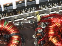
Opened the case and found 6 of the 8 Power supply FETS burnt. The other 2 at the end of the board don't look burnt but have not tested them.
I already ordered 8 IRF3205 FETS, and 8-10 ohms resistors (color Brown, black, black, gold). Also ordered the PWM UC3525ADW. My question is: the vertical board that drive the FETS, also have 2 additional CHIPS LM311 and LM358. Will these chips need to be replace? What is the purpose of these other chips.
Thank you for your help.
Darrel
This appears to be the same as the 500/1. If it is, it's VERY rare that anything on the driver board is damaged. If it has the drivers (Q608-Q611) in front of the PS FETs, they sometimes fail. When they have been stressed, they generally have overheated solder that's obvious.
It's common for the output FETs to fail, causing the power supply to fail. Check the outputs before powering up the amp after replacing the PS FETs.
It's common for the output FETs to fail, causing the power supply to fail. Check the outputs before powering up the amp after replacing the PS FETs.
Attachments
NTP6413ANG is the part number. It's obsolete. If they're defective, there are others that should work.
You can check the FETs in the circuit. If they're shorted, that's easy to see with them in the circuit. If they're leaky (less common failure), they may have to be removed to see the leakage. If they're not shorted, they're likely OK.
You can check the FETs in the circuit. If they're shorted, that's easy to see with them in the circuit. If they're leaky (less common failure), they may have to be removed to see the leakage. If they're not shorted, they're likely OK.
In the future, ask before ordering any substitute output transistors for a class D amp. This amp isn't as finicky as some but for some class D amps, substitutes that should work will not and the amp will not be reliable.
The nearby driver transistors, the SMD resistors and the driver IC (U500) sometimes fail.
There are a lot of threads for the 500/1 on the forum. Do a search for that amp and read through some of the threads.
The nearby driver transistors, the SMD resistors and the driver IC (U500) sometimes fail.
There are a lot of threads for the 500/1 on the forum. Do a search for that amp and read through some of the threads.
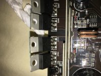
With the output FETs out of the board, connect two jumpers as shown below. Apply remote and after a couple of seconds, remove remote voltage and check the signal on pad 1 for all 4 of the outputs. There should be a square wave for about 10 seconds after removing remote voltage.
The power supply FETs don't have to be in the circuit.
Set the scope to 5v/div, DC coupling and 5us/div. Align the trace to the reference line before checking the waveforms.
The power supply FETs don't have to be in the circuit.
Set the scope to 5v/div, DC coupling and 5us/div. Align the trace to the reference line before checking the waveforms.
Attachments
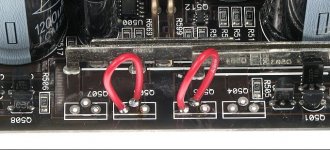
Well I read several times the section on the oscilloscope at your website. This is not exactly my terminology. I have a Hitachi V-252 with a slanted display. I think it fell off. Q504(pad 1)- 14v, Q505- 0v then at the end 4v, Q506- 28v, Q507- 0v. I never saw a square wave. I think that was either my set-up or the instrument.
If you notice any huge mistake in what I'm doing, please let me know. Where should I attach the alligator clip?
Thank you again.
Darrel
If you notice any huge mistake in what I'm doing, please let me know. Where should I attach the alligator clip?
Thank you again.
Darrel
Thank you Perry. Would you say the Chip at the U500 is bad? Why do I have this different readings from each pad? Could it be the driver transistors? What is the driver voltage at the gate of each transistor? Do they run in parallel for each channel?
I will try to get readings with some attached images to check on this chip.
Thank you
Darrel
I will try to get readings with some attached images to check on this chip.
Thank you
Darrel
- Status
- This old topic is closed. If you want to reopen this topic, contact a moderator using the "Report Post" button.
- Home
- General Interest
- Car Audio
- JL 600/1 v3 failure