I have a T40001bd that I have replaced the FETS on the audio board and rebuilt the driver circuits. The unit powers up fine and produces a clean audio signal with no load up to about 35 to 40vac. If gain is adjusted any higher the bottom portion of the 60hz test tone starts getting fuzy and distorted and the begins to draw excessive current. Now the gain knob is acting erratic so I am going to replace that but I don't feel like this is the problem. When the amp came in for repair the large choke on the output of the amp had to broken leads, I stripped them and re soldered them back down. Has anyone seen this problem?
I will check the signal on pin 3 when I get home. To answer the second question indirectly, I was kinda thinking on the page so I adjusted close to the point of distortion and then I adjusted the crossover knob to raise the output and it did the same thing. I will however u will try increasing the drive signal too.
Perry,
I checked drive signal on pin 3 of U107 and it did not distort while adjusting the gain. I also tried adjusted the amp gain up and then adjusting the drive signal higher and it still distorted. At around 30 to 38vac and starts to draw excessive current. When this happens it start to have a high pitch noise.
I checked drive signal on pin 3 of U107 and it did not distort while adjusting the gain. I also tried adjusted the amp gain up and then adjusting the drive signal higher and it still distorted. At around 30 to 38vac and starts to draw excessive current. When this happens it start to have a high pitch noise.
First I need to replace the 20k gain pot. I can't adjust it because it is not linear at all. It's very touchy and I am hopi g this the whole problem but I am sure it is deeper than that. Originally the output inductor 2 wires were snapped off at the board. I stripped off the varnish and re soldered them back to the board. When looking at the scope 60hz signal the bottom portion of the waveform starts to get choppy when current starts to draw. As i increase it even more the waveform goes off scale from noise. How do I check for Witching frequency through inductor? Do I set the scope for dc voltage at 2 us and place probe on the output?
The switching frequency of the output stage is the square wave frequency at the input to the inductor. Under normal operation, that will not be seen at the output. If the inductor is defective, the input square wave will pass through the inductor more than it should. If you removed turns from the inductor (don't know if you removed turns when you repaired it) it could be saturating. Inductors aren't gnereally designed so close to the edge that 2 turns would make a difference but it's possible. Adding a few turns would tell you if that's the problem.
The output inductor works with the large mylar caps so if those are defective (leaking at higher voltage, one or more with broken leads...) that could be the problem.
It's also possible that there is a problem with the drive circuit.
The output inductor works with the large mylar caps so if those are defective (leaking at higher voltage, one or more with broken leads...) that could be the problem.
It's also possible that there is a problem with the drive circuit.
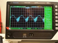
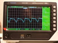
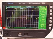
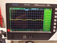
Perry I replaced the gain pot and the definitely fixed the erratic gain control but didn't fix excessive current draw after turn gain to an output of around 30 vac no load. I have included two pics one on the output with a 60hz signal driven to a point where it begins to have an arcing sound on the set of fets closet to the output terminal draw excessive current. The next pic the scope set to dc to try and capture high frequency during the problem. Time constant is not the same as the drive signal though but there is something..
Remove the red and blue wires that connect the two boards. Power up the amp and confirm that the voltage across those terminals on the PS board doesn't exceed the rated voltage of the rail caps. If it does, stop there.
Discharge the rail caps on the audio board with a dummy load or other large limiting resistor.
Look at the gate signal on all of the audio FETs. You should see a relatively good square wave that has an amplitude of about 8-10v. IF you can't see the waveform on the audio switchers, connect a load across the speaker terminals.
Perry I I checked the high voltage and it is running at
212 v. I removed D11 and that dropped it to 145 v which is weird cause that usually immediately drops it to ~100v. Can you explain to me how the voltage is higher. Are the step Transformers turned for 100v out?
Even at a the lower voltage to the audio board it distorts at at~30 on the output. I will check for a square wave on the input of the rail switchers. Yesterday I was probing one of the lm6162 ic looking for the triangle carrier wave and the distortion/high frequency noise stopped and I was able to adjust the gain higher but still could here random ticking. I replaced that ic this morning but this new scope I am not impressed with. With my handheld fluke I had no problems. This one it seems to be more noisy and I seem to chase my tail alot because the scope acts funny. I could not get the scope to show the carrier waveform this morning either.
There are several regulators in these amps and two of them are generally not working (so it seems from helping others, I won't repair these).
The only thing that's important about the rail voltage without the red/blue wires it to prevent blowing the rail caps. The output stage will (should) have no voltage.
There will be no rail-rail carrier without rail voltage.
Doing this is simply to allow the checking of the drive signals to see if they're the correct amplitude and similar on all FETs. This is difficult to do with the outputs swinging rail-rail.
This is also safer because slipping with the scope or meter probe typically won't do any significant damage. With the outputs operating normally (with rail voltage) a slip can cause severe damage.
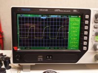
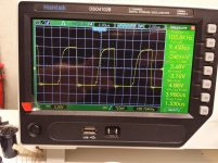
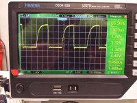
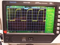
Okay Perry here are 2 pics of the drive signal on the rail switchers. The left pic is from Q413 and the drive signal is smaller in amplitude but cleaner and not square. The other pic is the drive signal for Q418. It has more amplitude but seems to be noisy towards the bottom. Also I noticed adjusting the gain changed the shape of the drive signal until it recovered and went back to normal.
These should be a nice square wave correct? I did replace the UC3526ADW yesterday. Powersupply has a high pitch squeal to it
These should be a nice square wave correct? I did replace the UC3526ADW yesterday. Powersupply has a high pitch squeal to it
Attachments
That's from only two of the 4 drive groups.
Without DC coupling and a ground reference, it's difficult to tell much. Leave the scope on DC coupling unless it's absolutely necessary to go to AC coupling.
The falling edge is what's critical. The rising edge is curved but normal with the FETs loading them.
The noise where the falling edge reaches its lowest point may be due to the inductor. If you ground the 3rd leg of the FETs being scoped, it may clear up. Ground it through a current limiting resistor to confirm that there is no problem grounding it. If it has no problem after connecting the limiting resistor, you should be able to ground your scope probe to the 3rd leg of the FET.
- Status
- This old topic is closed. If you want to reopen this topic, contact a moderator using the "Report Post" button.
- Home
- General Interest
- Car Audio
- Rockford Fosgate T40001bd