Ok, but just a last bit of guidance to assist me going forward as I continue digging.
The positive voltage that finally makes it to pin 13 in order to drive down pin 14, I know it makes its way through several resistors before being switched on and off by a transistor, but does that come directly from the +12v terminal or the +remote terminal?
I would assume that one of these two power sources would be where the low voltage would have to come from since nothing else in the amp is initialized yet.
I want to try tracing pin 13 starting from the other end to see where it is either interrupted, or it meets a strong ground that pulls it down, not allowing it to build up enough to drive down pin 14.
I noticed you used the word "charges", can that mean that a capacitor within this same circuit may not be doing its job properly, and that maybe I should turn my attention towards capacitors as the possible problem?
Also, do you have any other pics, illustrations, or diagrams that explain the low voltage power supply operation in the 300/4? The circuits are very similar, but just not labeled in the 450/4 and more complicated by having two supplies. I may be able to make sense of the 450/4 by studying the 300/4. Thanks again.
Also, do you have any other pics, illustrations, or diagrams that explain the low voltage power supply operation in the 300/4? The circuits are very similar, but just not labeled in the 450/4 and more complicated by having two supplies. I may be able to make sense of the 450/4 by studying the 300/4. Thanks again.
So, do you have any other pics, illustrations, or diagrams that explain the low voltage power supply operation in the 300/4, or any JL slash amp?
When pin 14 gets driven low, what happens next in the amplifier?
I am hoping to make sense of the 450/4 by studying other slash amps. Thanks.
When pin 14 gets driven low, what happens next in the amplifier?
I am hoping to make sense of the 450/4 by studying other slash amps. Thanks.
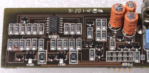
Thanks for the 500/5 pic. Maybe you may be familiar enough to explain a few things, if possible. I may be off-base but I am trying...
The power to pin13 is coming from the transistor with the red marking?
What is that transistor connected to for power, B+ or Remote+ terminal? I see it is connected to a pin on P800 ,and a 10k resistor that is connected to another capacitor with the + sign marking and a zener diode.
The power to pin13 is coming from the transistor with the red marking?
What is that transistor connected to for power, B+ or Remote+ terminal? I see it is connected to a pin on P800 ,and a 10k resistor that is connected to another capacitor with the + sign marking and a zener diode.
Ahh, progress. Good news and bad news.
Good news: I found a bad via coming from B+. I had to remove the plastic four pin connector that goes to the led display and repair it under there. I now get pin13 to go higher than pin12 and pin14 drops down. I now have three leds lit on all four driver boards and they get warm. I am also seeing +45v and -45v at the large 4.7k resistors which come from the eight 220uf caps.
Bad news: I still have no led lights lighting up on the display. I have 0.06v at the driver resistors for the PS fets.
I am still digging and will start to trace back from the driver resistors, but am unsure exactly where to look and what to look for. Maybe you can assist me further from here...
Reading some other JL amp threads and have some more readings for consideration:
Went tracing the PS driver transistor signal back to the IP3525AD on the vertical driver boards and found that pin1 pin10 and pin12 are all connected, if that is supposed to be so.
Both IP3525AD that are on the PS driver boards have 5.0v on pin16 and 10.4v on pin15.
IP3525AD readings:
Pin 1: 0.00
Pin 2: 4.9
Pin 3: 0.1
Pin 4: 0.1
Pin 5: 1.6
Pin 6: 3.7
Pin 7: 1.6
Pin 8: 0.9
Pin 9: 5.1
Pin 10: 0.0
Pin 11: 0.6
Pin 12: 0.0
Pin 13: 10.2
Pin 14: 0.6
Pin 15: 10.3
Pin 16: 4.9
The new readings on the LM324:
Pin 1: 0.8
Pin 2: 6.6
Pin 3: 4.0
Pin 4: 11.2
Pin 5: 6.6
Pin 6: 5.9
Pin 7: 10.0
Pin 8: 10.1
Pin 9: 6.6
Pin 10: 8.6
Pin 11: 0
Pin 12: 4.26
Pin 13: 5.8
Pin 14: 0.8
On the center legs of SF1604G and SF1604GA i am seeing +7.4 and -7.4 for the rear channels and +8.6 and -8.6 on the front channels.
Seeing 86v at the two first pins on the vertical driver cards with the 3 leds.
Just probing around taking random readings hoping to stumble upon something, while seeking help.
Seeing 86v at the two first pins on the vertical driver cards with the 3 leds.
Just probing around taking random readings hoping to stumble upon something, while seeking help.
So, i thought I would just try to run some audio through the amp and all four channels play, but very low and hollow sounding. It sound like I am listening only to the rear speaker output in a DSP Center Stage System because it plays some frequencies and instruments clearly, but the voices and vocals are like echoes in the background. I assume it is playing with the 7.4v rail voltage I have going to the rear outputs and 8.6v I am reading at the front outputs rail. I still only have 0.05 on the first leg of the PS fets and no power led on the top-mounted display. It's like I brought back a pulse, but the amp is in a coma, and I am trying to wake it up. Hope I don't cause anybody any pain with my analogy, but that's what it's like.
Digging around the PS driver card and thought I would post the voltage on the input pins. Also found that pin11 and pin14 are the output to the driver transistors. I have 0.06 on that pin.
PS driver board pin readings from left to right (components facing you)
1) 0.5
2) 0.5
3)-0.00
4) -0.00
5) 0.8
6) -0.00
7) -0.00
8) -0.00
9) 0.6
10) 0.1
11) 5.2
12)0.6
13) 11.2
14) 0.6
15) 4.9
PS driver board pin readings from left to right (components facing you)
1) 0.5
2) 0.5
3)-0.00
4) -0.00
5) 0.8
6) -0.00
7) -0.00
8) -0.00
9) 0.6
10) 0.1
11) 5.2
12)0.6
13) 11.2
14) 0.6
15) 4.9
1.2v on pin 16 of U605
I don't have any usable voltage going to any of the op-amps for front or rear channels. I have 43v and 15v at the power supply with the yellow transformer and it is warm to the touch. I suspect the 15v is not reaching the op-amp power circuit.
U605 voltages
1) 1.1
2) 0.0
3) 1.1
4) 1.1
5) 0.0
6) 1.1
7) 1.1
8) 0.0
9) 0.0
10) 1.1
11) 1.1
12) 0.0
13) 1.1
14) 1.1
15) 1.1
16) 1.1
Can you describe what it looks like? Is it a regular TO-220 transistor? There is a transistor right next to the yellow transformer where the 43v and 15v are being produced.
Or is it one of the components that is mounted in line with the outputs, power FETs, and regulators along the heatsink?
Or is it one of the components that is mounted in line with the outputs, power FETs, and regulators along the heatsink?
Attachments
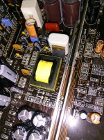
I don't know what it looks like. The other amps of the same series have them. Some are TO-220. Others are smaller. I don't see it in the photos I have. That's why I thought is may be clamped to the sink.
The TO-220 transistor next to the transformer drives that transformer.
The TO-220 transistor next to the transformer drives that transformer.
OK, to help me find it, can you answer these questions:
Where does the 5v regulator get its power from? The 15v power supply or the B+?
And, where does it then send its regulated 5v output?
The op-amp power that I am missing comes from where?
What pins are power and ground on the PS op-amps?
Where does the 5v regulator get its power from? The 15v power supply or the B+?
And, where does it then send its regulated 5v output?
The op-amp power that I am missing comes from where?
What pins are power and ground on the PS op-amps?
- Status
- This old topic is closed. If you want to reopen this topic, contact a moderator using the "Report Post" button.
- Home
- General Interest
- Car Audio
- Need help with dead JL Audio 450/4