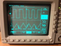
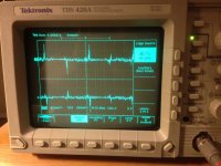
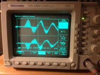
Well, you have a serious power supply problem, there's about 10V of crap coming through at ~100kHz. Given the asymmetry of the the waveform, I'm going to guess that the fault is with the latter part of the PSU switcher, i.e. after the switching transformer. I could be totally wrong here, but have a look for shorts (due to gunk from the exploded caps) and bad/open/shorted components (diodes, capacitors) in the rectifier+filter stages of the PSU.
Ok, I didnt notice this till just a bit ago, but the ground wire I hooked to the grounds on the probes has a voltage reading and is not the same as the B- terminal. Which I dont understand because it is a ground wire to the amplifier case. But now when I try and hook up the probes grounded to the B- terminal the voltage goes to high on probe 1 and off the scale on the oscilloscope. I can only go up to 10 volts on the oscilloscope. Not sure what to do to get measurement? Also I get -22.50 volts From B- to positive speaker wire, But just millivolts when its hooked up to neg speaker and positive speaker. Where should I connect the oscilloscope probe grounds? Is B- correct? And how can I adjust oscilloscope to measure over 10 volts? Autoset isn't doing it.
Thanks
Ignore B+ and B-, they're quite possibly floating depending on the amp's supply design, or at least not centred on "zero". The amplifier's case is probably a good bet, or maybe if you can find a track labelled "GND" on the circuit board. It's likely your amp has a 55V supply, which would put the speaker terminals at 22.5V each (wrt B-) with no signal, and they will probably swing symmetrically around that centre-point.
If you want to measure higher voltages, you can use a 10x probe.
If you want to measure higher voltages, you can use a 10x probe.
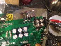
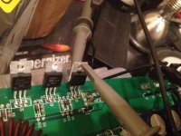
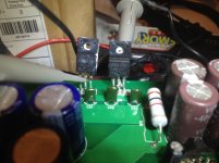
This is the ground wire I had connected to. It has GD marked on the board beside it. So where should I go from here? If I flex the board a little it does make a little difference in the static. So im thinking a loose connection maybe? Is there anythying else I can do to narrow it down a little?
Attachments
Im not going to find schematics on this, there has to be another way. I reconnected that ground wire and switched probe 1 to 10x and probe 1 is on the middle leg of outputs and probe 2 on pos speaker and this is what I got.
Attachments
Hello! Can you please take the waveform of the +- rail voltages? You can use the black wire hanging around on your amp as your reference.
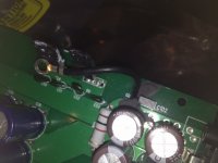
Ok, Just to make sure Im hooked to the right places I took a picture of connections. Also do the settings look ok on the oscilloscope?
Thanks
Attachments
Ok, Just to make sure Im hooked to the right places I took a picture of connections. Also do the settings look ok on the oscilloscope?
Thanks
probe 1 is in the gate? and probe #2 is in the rail? either you may have problem.
probe 1 is in the gate? and probe #2 is in the rail? either you may have problem.
Probe 1 was connected to the drain or collecter of the irfb31n20dpbf and probe 2 was connected to the gate. I'm not really sure where to find rail + and -, everywhere I test I get AC voltage of around 60 volts.
Also probably a dumb question but should all the output transistors be the same kind or should they be half pnp and half npn types?
Drain and collector are not the same. FET and BJT transistors. IRFB31n20 is FET. Yes half may N or P channel depends.
If not written as "-rail" or "+rail", you may found the rail voltages across the big capacitors, one leg of the capacitor is connected either the drain or source of the output FET depending to topology.
Please start reading this website
http://www.bcae1.com/ , this is easy to learn and very very nice reference. Everything you will found here.
Please send me an email armand_jr2001@yahoo.com if you have any questions, ill try to assist you as I can but I still have limited knowledge in repairing amps.
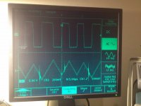
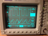
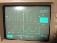
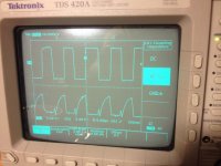
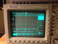
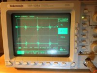
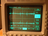
Ok, I did some research and found my rail voltages. I also found another issue, my voltages aren't matched. -74 vdc on one and +64 on the other rail, about a 10 volt difference. So here are the oscilloscope pictures hooked up correctly, probe 1 connected to neg. rail and probe 2 connected to pos. rail. Also that ground wire would not work for rails, had to connect to B- to get voltage. One of the pictures is AC and one is DC on oscilloscope. If you have any idea's please let me know, this is driving me nut's. With the different voltages I am wondering now if I do have toroidal winding problem.?
Attachments
Ok, I did some research and found my rail voltages. I also found another issue, my voltages aren't matched. -74 vdc on one and +64 on the other rail, about a 10 volt difference. So here are the oscilloscope pictures hooked up correctly, probe 1 connected to neg. rail and probe 2 connected to pos. rail. Also that ground wire would not work for rails, had to connect to B- to get voltage. One of the pictures is AC and one is DC on oscilloscope. If you have any idea's please let me know, this is driving me nut's. With the different voltages I am wondering now if I do have toroidal winding problem.?
Please connect the black probe to negative speaker terminal or at the VSS of the secondary windings. It will correct the reading.
Please connect the black probe to negative speaker terminal or at the VSS of the secondary windings. It will correct the reading.
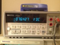
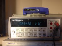
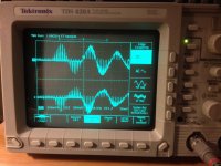
Thank you! I found a good ground by neg speaker close to where that ground to chassis was, that ground had a small cap connected to it and I think that is why it wouldnt work. Anyways here are some more photos correctly hooked up. The first ones are high pitch tone with static after amp is on a minute static goes away and leaves just high pitch tone and then I took the last two pics.
Attachments
 English, please!
- Status
- This old topic is closed. If you want to reopen this topic, contact a moderator using the "Report Post" button.
- Home
- General Interest
- Car Audio
- Help: Boss CE-3800D "Static and whining noise"