Hello All!
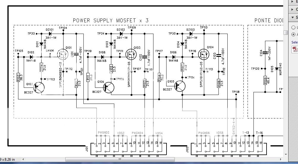
Good Day! I'm repairing the Audison LRx4.1K amp from customer with blown all 6pcs of 80N06 power transistors. Now I'm planning to upgrade these transistors with IRF3205, do you think this is possible? If yes are there any resistors that also need to be replaced?
Also can I use 5% resistors for all blown resistors in power supply? installed resistors are 1% tolerance with 21.5Ohms.
Thanks and more power to this forum!
Good Day! I'm repairing the Audison LRx4.1K amp from customer with blown all 6pcs of 80N06 power transistors. Now I'm planning to upgrade these transistors with IRF3205, do you think this is possible? If yes are there any resistors that also need to be replaced?
Also can I use 5% resistors for all blown resistors in power supply? installed resistors are 1% tolerance with 21.5Ohms.

Thanks and more power to this forum!
Last edited:
Audison does not see much daylight on this forum. I have a similar document for the 5.1k and they did fair job of engineering that circuitry to drive each fet individually.
My best suggestion is for you to rebuild only one fet per toroid winding with your mods and give it a try. You see the amp can run at idle with only two fets in circuit, One for each toroid winding. This will allow you to test your alterations in the safety of minimal parts count and possible parts loss if your alterations don't pan out. Plus you can scope your gate signals to see how they look.
.
The circuitry looks to be very capable of the 3205 mosfet. The gate resistor value is low enough to be workable. They used 1% values because in the manufactures world they cost about the same and 5% parts do considering the volumes they consume building amps, plus any engineer will default to the highest quality when ever possible. So unless you test it and see otherwise %5 and 3205 might be a nice alteration.
Have you compared the gate capacitance values between the fets from the factory spec sheets? If they are way off then you might be in for some rethinking, and rework. Oh and if it works fine with one pair and draws too much idle current with all mosfets loaded then your gate resistor is the place to start as its likely the wrong value for that fets gate capacitance and its going to go nutz and draw too much current if it isn't correct. seen this a few times over the years...
But again I stress only do a pair of fets, one per toroid winding as a test. I know how this amp is assembled and yes its a lot of work to put it back together. Perhaps if your time is limited it would be best to just order the correct value replacement parts.
Audison does not see much daylight on this forum. I have a similar document for the 5.1k and they did fair job of engineering that circuitry to drive each fet individually.
My best suggestion is for you to rebuild only one fet per toroid winding with your mods and give it a try. You see the amp can run at idle with only two fets in circuit, One for each toroid winding. This will allow you to test your alterations in the safety of minimal parts count and possible parts loss if your alterations don't pan out. Plus you can scope your gate signals to see how they look.
.
The circuitry looks to be very capable of the 3205 mosfet. The gate resistor value is low enough to be workable. They used 1% values because in the manufactures world they cost about the same and 5% parts do considering the volumes they consume building amps, plus any engineer will default to the highest quality when ever possible. So unless you test it and see otherwise %5 and 3205 might be a nice alteration.
Have you compared the gate capacitance values between the fets from the factory spec sheets? If they are way off then you might be in for some rethinking, and rework. Oh and if it works fine with one pair and draws too much idle current with all mosfets loaded then your gate resistor is the place to start as its likely the wrong value for that fets gate capacitance and its going to go nutz and draw too much current if it isn't correct. seen this a few times over the years...
But again I stress only do a pair of fets, one per toroid winding as a test. I know how this amp is assembled and yes its a lot of work to put it back together. Perhaps if your time is limited it would be best to just order the correct value replacement parts.
Thank you so much! I enlightened and learned a lot.
I've tested the amp with complete set of 3205 and 5% resistors
") it was built before I read your suggestions.
it was built before I read your suggestions. The amps shows fuse good without protection and measured +-36V rail to rail from at the bank capacitors. But measuring rail voltages is doesnt appear from the terminal of the output FETS. Why I dont have these rail voltages from the output FETS? Are there any switch to supply the output FETS? anyway I'll try to re-read schematics.
Second, when I scoped the gate of the power FETS(3205) It appears square wave waveform but less than a second it cycled to nothing then comes back. I think it tries to give power then goes to protect and powered it again. Using voltmeter from the gate terminal, I reads from 7 to 8V cycled.
Do you think 3205 is mismatch for this power board? I searched for the input capacitance, is this the input capacitance right? the 3205 shows 3247pF while 5110pF, they are almost 2nF way off. Do you think this is the culprit of the cycled power?
Thank you! more power to this forum!
Last edited:
Well no I don't think the 3205's are causing your protection faults. How many channels does this amp have 4 or 5 ??? If its 5 then I am of the thinking your sub channel might be damaged causing the protection triggering because most 5 channel amps have their sub channels damaged. Very rarely is there anything else wrong with 5 channel amps. If its a four channel amp then we will need to look at them to see if any are damaged. The audison amps I have worked on all have very high voltage rails < +&-80 VDC rails > compared to average car amps and so they use very tight protection to prevent speaker damage.
Send me a PM so I can exchange my email with you so you can share your 4.1 print we me please. I doubt my 5.1 k document will be of much help
Send me a PM so I can exchange my email with you so you can share your 4.1 print we me please. I doubt my 5.1 k document will be of much help
Well no I don't think the 3205's are causing your protection faults. How many channels does this amp have 4 or 5 ??? If its 5 then I am of the thinking your sub channel might be damaged causing the protection triggering because most 5 channel amps have their sub channels damaged. Very rarely is there anything else wrong with 5 channel amps. If its a four channel amp then we will need to look at them to see if any are damaged. The audison amps I have worked on all have very high voltage rails < +&-80 VDC rails > compared to average car amps and so they use very tight protection to prevent speaker damage.
Send me a PM so I can exchange my email with you so you can share your 4.1 print we me please. I doubt my 5.1 k document will be of much help
It's a 4 channel, Caps voltage rating is just 50VDC. Ok ill gonna check the 4 channels then PM you. Thanks!
LRX 5.1K
Can you send me a copy of the LRx 5.1K schematic?
Audison does not see much daylight on this forum. I have a similar document for the 5.1k and they did fair job of engineering that circuitry to drive each fet individually.
My best suggestion is for you to rebuild only one fet per toroid winding with your mods and give it a try. You see the amp can run at idle with only two fets in circuit, One for each toroid winding. This will allow you to test your alterations in the safety of minimal parts count and possible parts loss if your alterations don't pan out. Plus you can scope your gate signals to see how they look.
.
The circuitry looks to be very capable of the 3205 mosfet. The gate resistor value is low enough to be workable. They used 1% values because in the manufactures world they cost about the same and 5% parts do considering the volumes they consume building amps, plus any engineer will default to the highest quality when ever possible. So unless you test it and see otherwise %5 and 3205 might be a nice alteration.
Have you compared the gate capacitance values between the fets from the factory spec sheets? If they are way off then you might be in for some rethinking, and rework. Oh and if it works fine with one pair and draws too much idle current with all mosfets loaded then your gate resistor is the place to start as its likely the wrong value for that fets gate capacitance and its going to go nutz and draw too much current if it isn't correct. seen this a few times over the years...
But again I stress only do a pair of fets, one per toroid winding as a test. I know how this amp is assembled and yes its a lot of work to put it back together. Perhaps if your time is limited it would be best to just order the correct value replacement parts.
Can you send me a copy of the LRx 5.1K schematic?
- Status
- This old topic is closed. If you want to reopen this topic, contact a moderator using the "Report Post" button.
- Home
- General Interest
- Car Audio
- LRx 4.1K Audison amp