So have this cyclops. At first it was constantly going into protect. There was a flash of DC on the output terminals as it would protect. While in protect I got the following measurements:
KA7500BD
Pin 1: 5.78
Pin 2: 2.546
Pin 3: 4.68
Pin 4: 3.983
Pin 5: 1.575
Pin 6: 3.676
Pin 7: 0.00
Pin 8: 12.16
Pin 9: 0.000
Pin 10: 0.000
Pin 11: 12.16
Pin 12: 12.16
Pin 13: 4.97
Pin 14: 4.97
Pin 15: 4.97
Pin 16: 0.000
LM293D
Pin 1: 6.37
Pin 2: 2.483
Pin 3: around 4v (Please see note below)
Pin 4: 0.000
Pin 5: 1.025
Pin 6: 2.944
Pin 7: 0.116
Pin 8: 12.15
Note about pin 3 on LM: It started out around 4v again like the AQ if I held the lead on the pin long enough it would eventually "drain" to below 2v and turn off the protection then relays would click on then voltage jumps back up and go back into protect and turn relays off again.
So after trying this a few times to get readings, I got it to stay out of protect. Using the current limiter. So I rechecked voltages at various locations heres what I have.
KA7500BD -------- -----------------------LM293D
Pin 1: 0.004 -----Pin 16: 0.003 ------- Pin 1: 0.070
Pin 2: 2.163 -----Pin 15: 4.470 -------Pin 2: 2.271
Pin 3: 0.075 -----Pin 14: 4.470 -------Pin 3: 1.800
Pin 4: 0.075 -----Pin 13: 4.470 -------Pin 4: 0.003
Pin 5: 1.372 ---- Pin 12: 5.45 ---------Pin 5: 0.945
Pin 6: 3.103 -----Pin 11: 5.45 ---------Pin 6: 2.710
Pin 7: 0.003 -----Pin 10: 1.785 ---- ---Pin 7: 0.070
Pin 8: 5.420 -----Pin 9: 1.782 ----- --- Pin 8: 5.46
IRFP064N: Leg 1: 1.6v ......Leg 2: 8.2v ................................Leg 3: 0.000v
Rectifiers: Leg 1: 68.5v ......Leg 2: pulses display of dmm .. Leg 3: 68.7v
IFRP360LC: Leg 1: 50v .....Leg 2: 68.5v ..............................Leg 3: 51v
I have the following readings on the output drive card pins:
Pin 1: -51.0v ...............Pin 8: 1.846 .............Pin 15: -68.6
Pin 2: -51.2v .............. Pin 9: 5.03 .............. Pin 16: -68.2
Pin 3: -68.5v .............. Pin 10: -5.42 ...........Pin 17: -68.6
Pin 4: -58.7v ...............Pin 11: 0.000 ..........Pin 18: -58.7
Pin 5: -68.6v ...............Pin 12: -5.10 ..........Pin 19: -68.6
Pin 6: -68.1v ...............Pin 13: 5.00 ...........Pin 20: -51.4
Pin 7: -68.6v ...............Pin 14: 8.73 ...........Pin 21: -51.3
...and there is over 40vdc on the output speaker terminals when relays are engaged.
Now after leaving my resistor cool, and recharging my battery. I can't get it to stay out of protect again. Back to point one.
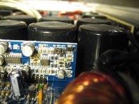
This pic shows a spot on the PS driver card thats not looking too good or was repaired before and not cleaned up well.
KA7500BD
Pin 1: 5.78
Pin 2: 2.546
Pin 3: 4.68
Pin 4: 3.983
Pin 5: 1.575
Pin 6: 3.676
Pin 7: 0.00
Pin 8: 12.16
Pin 9: 0.000
Pin 10: 0.000
Pin 11: 12.16
Pin 12: 12.16
Pin 13: 4.97
Pin 14: 4.97
Pin 15: 4.97
Pin 16: 0.000
LM293D
Pin 1: 6.37
Pin 2: 2.483
Pin 3: around 4v (Please see note below)
Pin 4: 0.000
Pin 5: 1.025
Pin 6: 2.944
Pin 7: 0.116
Pin 8: 12.15
Note about pin 3 on LM: It started out around 4v again like the AQ if I held the lead on the pin long enough it would eventually "drain" to below 2v and turn off the protection then relays would click on then voltage jumps back up and go back into protect and turn relays off again.
So after trying this a few times to get readings, I got it to stay out of protect. Using the current limiter. So I rechecked voltages at various locations heres what I have.
KA7500BD -------- -----------------------LM293D
Pin 1: 0.004 -----Pin 16: 0.003 ------- Pin 1: 0.070
Pin 2: 2.163 -----Pin 15: 4.470 -------Pin 2: 2.271
Pin 3: 0.075 -----Pin 14: 4.470 -------Pin 3: 1.800
Pin 4: 0.075 -----Pin 13: 4.470 -------Pin 4: 0.003
Pin 5: 1.372 ---- Pin 12: 5.45 ---------Pin 5: 0.945
Pin 6: 3.103 -----Pin 11: 5.45 ---------Pin 6: 2.710
Pin 7: 0.003 -----Pin 10: 1.785 ---- ---Pin 7: 0.070
Pin 8: 5.420 -----Pin 9: 1.782 ----- --- Pin 8: 5.46
IRFP064N: Leg 1: 1.6v ......Leg 2: 8.2v ................................Leg 3: 0.000v
Rectifiers: Leg 1: 68.5v ......Leg 2: pulses display of dmm .. Leg 3: 68.7v
IFRP360LC: Leg 1: 50v .....Leg 2: 68.5v ..............................Leg 3: 51v
I have the following readings on the output drive card pins:
Pin 1: -51.0v ...............Pin 8: 1.846 .............Pin 15: -68.6
Pin 2: -51.2v .............. Pin 9: 5.03 .............. Pin 16: -68.2
Pin 3: -68.5v .............. Pin 10: -5.42 ...........Pin 17: -68.6
Pin 4: -58.7v ...............Pin 11: 0.000 ..........Pin 18: -58.7
Pin 5: -68.6v ...............Pin 12: -5.10 ..........Pin 19: -68.6
Pin 6: -68.1v ...............Pin 13: 5.00 ...........Pin 20: -51.4
Pin 7: -68.6v ...............Pin 14: 8.73 ...........Pin 21: -51.3
...and there is over 40vdc on the output speaker terminals when relays are engaged.
Now after leaving my resistor cool, and recharging my battery. I can't get it to stay out of protect again. Back to point one.
This pic shows a spot on the PS driver card thats not looking too good or was repaired before and not cleaned up well.
Attachments
Last edited:
K, I should prob mention that there is no protection light staying on. The top lights are on but no clip or protect. It blinks green then goes out completely.
I went over both the PS and output transistors and they seem OK in the circuit but having DC on the out terminals I'm doubting it...
I went over both the PS and output transistors and they seem OK in the circuit but having DC on the out terminals I'm doubting it...
 ... how would I check for that? ....
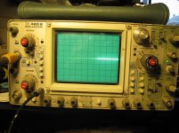
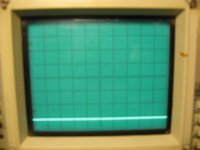
I don't know the exact configuration of the output stage but you should have a square wave that swings from one supply rail to the other on either the center or 3rd leg for all output transistors. You need to touch your scope to the legs and monitor the display from the time that you apply remote voltage. Set the scope to 20v/div and 2ms. If you see something that looks like a wide trace, set the time base to about 5us and see if there is a clean sine wave.
Should I be driving a signal into it for this test?
I'm not sure if there is or not... As soon as I touch the red prob to either pin the trace darts up off the screen. even if I set it to 50v/div. I tried black on both the center tap and batt ground terminal.
With the power applied (no remote) the DMM shows 0.040v on pins 1 & 3 and pin 2 as a slowly draining rail. Almost down to 1.5v now....
With remote applied using DMM I have -58.9v on pins 1 & 3 and 66.8v on pin 2. of 2 banks and -66.4v on pins 1&3 and -60v on pin 2 of the other 2 banks.
My settings:
Attachments
Last edited:
First pic is reading with prob on center leg of output transistor.
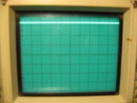
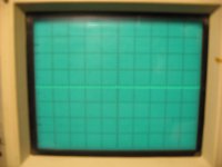
Second pic is reading with prob on 3rd leg
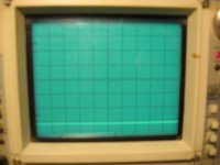
Third pic is probe on + speaker termial
4th pick is with probe on - speaker terminal
Second pic is reading with prob on 3rd leg
Third pic is probe on + speaker termial
4th pick is with probe on - speaker terminal
Attachments
I don't see any broken legs and they all test OK in the circuit. I haven't removed them to test... there are no shorts and they all pretty much read the same.
I have the following voltages on the output driver card pins.
1: -60v
2: -60v
3: -64v
4: -54.6v
5: -63.7v
6: -63.1
7: -63.5
8: 1.335
9: 5.03
10: -5.31
11: 0.000
12: -5.10
13: 5.0
14: 7.267
15: -63.5
16: -63.1
17: -63.5
18: -54.4
19: -63.6
20: -60.1
21: -60.2
Should I pull it out of the case and remove the outputs and test out of the circuit?
Last edited:
- Status
- This old topic is closed. If you want to reopen this topic, contact a moderator using the "Report Post" button.
- Home
- General Interest
- Car Audio
- Hifonics XXV-Cyclops repair