I got a Sony big red amplifier that I'm repairing. I've repaired a big red before,last one had shorted output fets.
This one tested fine for the power fets and audio fets. But had q901 blown, so i went ahead and replaced it, well now it cuts on and produce the 56v peak to peak rail voltage.
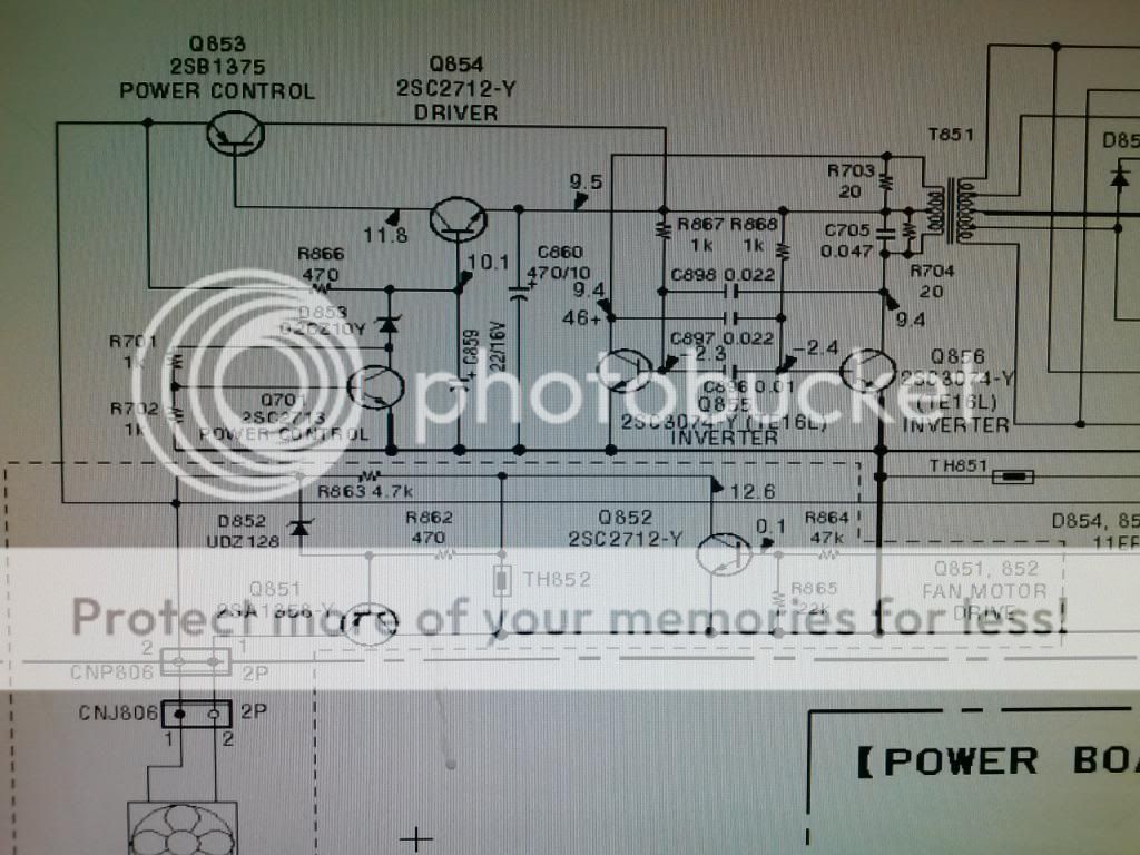
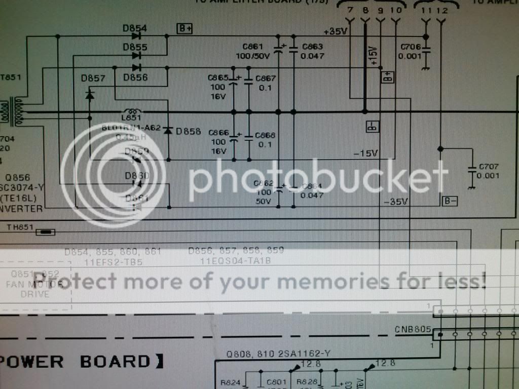
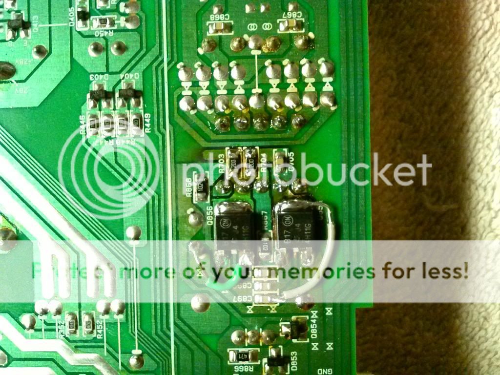
But i have no audio output, i checked the voltage for the OP amps (pin 4 and 8) and read millivolts. So i checked the pre stage power supply (which is on the amplifier board) and notice i only have 27.8v on the cathode of d854 and -27.8 on the anode of d860, but the schematics state i should be reading 45v.
I read .006v on the cathode of d856 (should be 15v) and got the same for anode of d859 (should be -15v).
I haven't checked the smd transistors that are located below the board. But I'm assuming i have a driver/inverter/or power control transistor that may be bad.
]
Please keep in mind that the small transformer on the pre amp power supply seems to run very hot because it left the board dark colored and all solder pads around it look pretty distressed. I've notice this on several big reds.
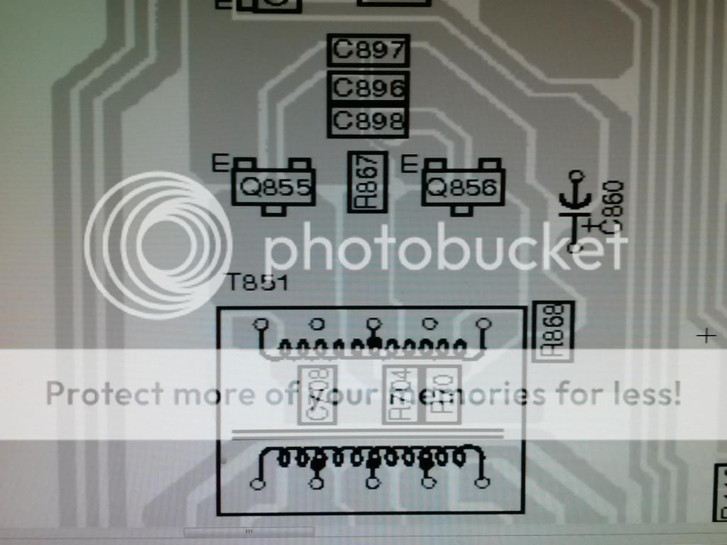
If you need schematics in order to help, pm me...i have them. Below are some pics if the schematics of the pre amp power supply.
Thanks in advance.
This one tested fine for the power fets and audio fets. But had q901 blown, so i went ahead and replaced it, well now it cuts on and produce the 56v peak to peak rail voltage.
But i have no audio output, i checked the voltage for the OP amps (pin 4 and 8) and read millivolts. So i checked the pre stage power supply (which is on the amplifier board) and notice i only have 27.8v on the cathode of d854 and -27.8 on the anode of d860, but the schematics state i should be reading 45v.
I read .006v on the cathode of d856 (should be 15v) and got the same for anode of d859 (should be -15v).
I haven't checked the smd transistors that are located below the board. But I'm assuming i have a driver/inverter/or power control transistor that may be bad.
]
Please keep in mind that the small transformer on the pre amp power supply seems to run very hot because it left the board dark colored and all solder pads around it look pretty distressed. I've notice this on several big reds.
If you need schematics in order to help, pm me...i have them. Below are some pics if the schematics of the pre amp power supply.
Thanks in advance.
This power supply provides the driver and low voltage regulated voltages. it does run very hot. The transistors under the board have likely failed or the solder connections are so bad that the supply will no longer oscillate.
To make the connections reliable, you'll need to add new solder, desolder them, remove the transformer if they still look questionable, clean up the pads and resolder. If there are traces/pads on the top of the board, you may want to solder from both the top and bottom of the board.
To make the connections reliable, you'll need to add new solder, desolder them, remove the transformer if they still look questionable, clean up the pads and resolder. If there are traces/pads on the top of the board, you may want to solder from both the top and bottom of the board.
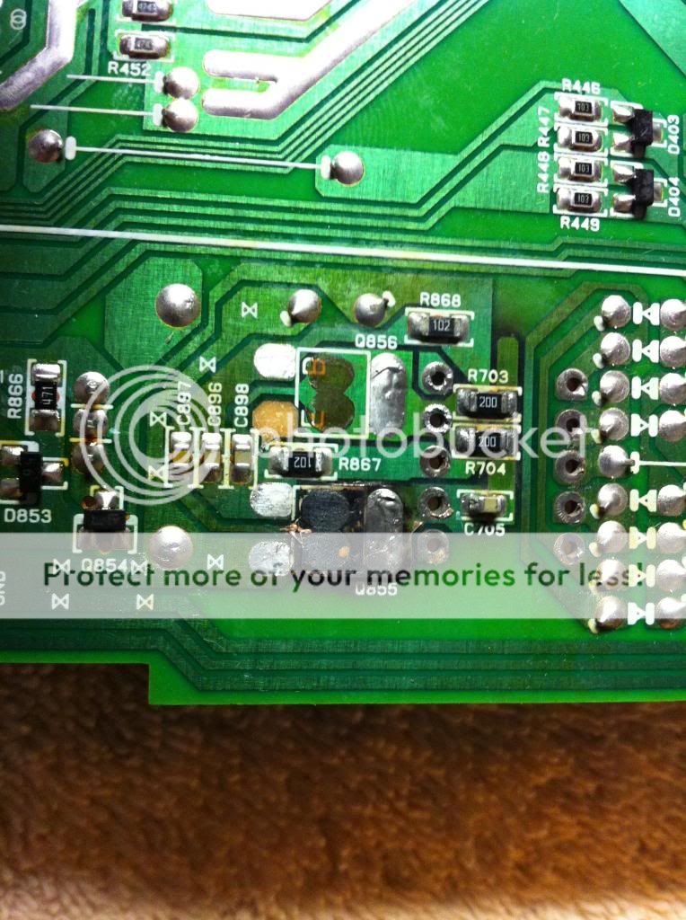
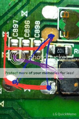
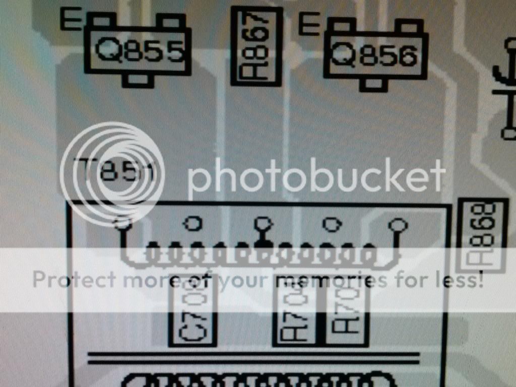
Looks like one of the inverter (q855) is blown or damage. I went ahead and removed both and transformer. Cleaned the pads and notice a broken/open trace on q855. Got the transformer back on board with new solder.
Is there a sub for q855 which is a 2sc3074-y . I know a supplier but its in Asia (2 week wait), mouser is 12 miles away but they don't carry discontinued components. Thanks.
I damaged a trace as well, as you can see in the pic but an going to use a jump wire that's insulated.
Last edited:
THIS transistor may work. Check the dimensions and compare to the originals.
If you can find a way to add some sort of a heatsink to this area, it may help the board to survive a bit longer. If they are close to the sink, thick thermal gap pad may help. If they are too far away for that, a block of aluminum and thermal gap pad may work.
If you can find a way to add some sort of a heatsink to this area, it may help the board to survive a bit longer. If they are close to the sink, thick thermal gap pad may help. If they are too far away for that, a block of aluminum and thermal gap pad may work.
Ok i replaced both inverters and jump wired the broken traces. So i put it back together and apply power, as soon as i applied the remote i could smell the flux smoking. It got quickly very hot, hot enough it was melting the solder. I used cardas quad solder which melts at 178c, pretty low temp.
Still no a audio output. What could be wrong, could it be the power control or drivers before q855?
Only inverter q855 got extremely hot. I didn't leave the remote on the amp for more than 3 seconds, i didn't want to damage the board any more than what it already was.
Still no a audio output. What could be wrong, could it be the power control or drivers before q855?
Only inverter q855 got extremely hot. I didn't leave the remote on the amp for more than 3 seconds, i didn't want to damage the board any more than what it already was.
Last edited:

'Leaky' means electrically leaky. They can short and open and also leak. Whey they leak, they pass current like a resistor or possibly a resistor in parallel with a diode.
The transformers do sometimes fail on these. This is one of those rare times when a ringer is useful. If you remove the transformer, do you read an open circuit between the primary and secondary circuits?
PacParts appears to have a replacement available if you find that this one is defective.
PacParts: Sony 1-435-149-11
Okay removed the transformer and checked it. Each side had continuity between the pins/legs and open between primary and secondary windings. So it seems okay to me, i don't have a ringer. I'll check the diodes later tonight to see if any are bad.
I'll remove them from the pcb.
I'll remove them from the pcb.
There is a good chance that the transformer is defective. Without a ringer, you could try connecting the primary windings of the small transformer to the primary windings of the main power supply. The center tap should be connected via a 2 ohm current limiting resistor. The outer primary windings (that connect to the two SMD transistors on the board) would connect to the outer primary windings of the main power supply transformer. If the 2 ohm resistor heats up quickly, the transformer is almost certainly defective.
Hey Perry do you know of any other old school Sony amps that have that same transformer? It would cost 45 bucks after shipping, if i can find a used amp with the same transformer i can swap it out and the left over amp for parts (screws, terminal blocks, transistor clamps, ect.).
No luck with any repair shops checking the transformer, so am going to test it the way you stated, one question though, does the amp board have to be attach to the power board when i power the power board up? I ask because i separated them, i don't think it would matter but thought i ask first.
No luck with any repair shops checking the transformer, so am going to test it the way you stated, one question though, does the amp board have to be attach to the power board when i power the power board up? I ask because i separated them, i don't think it would matter but thought i ask first.
I don't think that they have to be connected but I can't remember powering one up with them separated.
The only other amps that I know of that may use this part are the other XM-75x7 amps.
You could probably add a few turns to the main transformer as a substitute for this transformer.
The only other amps that I know of that may use this part are the other XM-75x7 amps.
You could probably add a few turns to the main transformer as a substitute for this transformer.
- Status
- This old topic is closed. If you want to reopen this topic, contact a moderator using the "Report Post" button.
- Home
- General Interest
- Car Audio
- Sony XM-7547, no output, help.