Hello, everyone,
I received this amp for repair, (as I await the arrival of parts for my other ampilicador ......)
Checked, all the transistors, both the output, such as the power source, and none is shorted, or give erroneous readings.
When connected, no sound from the speaker, only three seconds, there is a "clock" in the speaker, then go silent.
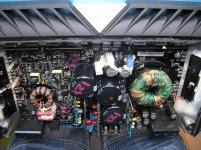
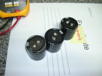
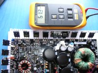
I noticed a little swollen capacitors of the power connection, I proceeded to take away, and I have noticed that on the board and under one (C1013) had a spark in the negative, which was also, in that capacitor (see photos)
I have measured their ability, and all I get 200uF less than its value, the latter including electrolytic capacitor, took longer to read me ...
I do not know if replacing the three capacitors, or only the latter, what do you think?
What may have been caused, that spark?
I received this amp for repair, (as I await the arrival of parts for my other ampilicador ......)
Checked, all the transistors, both the output, such as the power source, and none is shorted, or give erroneous readings.
When connected, no sound from the speaker, only three seconds, there is a "clock" in the speaker, then go silent.
I noticed a little swollen capacitors of the power connection, I proceeded to take away, and I have noticed that on the board and under one (C1013) had a spark in the negative, which was also, in that capacitor (see photos)
I have measured their ability, and all I get 200uF less than its value, the latter including electrolytic capacitor, took longer to read me ...
I do not know if replacing the three capacitors, or only the latter, what do you think?
What may have been caused, that spark?
Attachments
The spark was caused by having a bad solder connection. It appears that the trace for that capacitor is on the top of the board. If there is no trace (not referring to the pad, but a trace that goes to the other capacitors) you will need to restore the connection between the bottom of the board (the solder pad) and the trace on top of the board.
How do you like that meter?
How do you like that meter?
Well,
Then I reset the connection, apparently, there was a short between the top and the bottom of the motherboard.
(that of the welds bad .... I think more than one ...)
I repositioned the electrolytic capacitors in place, (either tinned)
When connected, (no speaker) apparently seems a good start ... but after three seconds, you hear a "click" near the LEDs, and attempts to power the red LED, and then hear a small sound sparkling, for the same area ...
Consumption is low: 1.1 A
Speaker Terminals: 0.4 v
Speaker connected to three seconds, I heard a "pow" big, moves the speaker cone to its limits, and then disconnect the battery, for fear of burning something ....
I'm a little lost ... the truth ... I do not know which way to go ...
Any ideas of where to keep checking?
How odd ....
I checked all the output MOSFET, and none has given me short, and not open ....
I have also checked U3 (TL072) (op amp, near the RCAS) is correct, + - 13v.
I think there are some more operational in the plates which are positioned vertically with respect to the motherboard, and are difficult to access ...
Maybe ask the scheme to Rockford ...
What do you think, Perry?
I changed a couple of emails with Rockford, unsuccessfully, it seems that you do not supply circuit diagrams ....
Well, I retired 4 MOSFET amplifier (Q2006, 2007,2008, and Q2009) I have checked, and seem to be good ....
I connected the amplifier, and interestingly, I still 14v. (decrease) in the speaker output (does not sound the previous sparkling sound)
I also checked some drivers (Q2005, 2002 and Q2004) that belong to the mosfet removed:
(tester negative probe to ground the amplifier)
Q2005:
B: 8.98
C: 0
E: 9.01
Q2002:
B: -4.20 V and decreasing
C: 4.70 V and decreasing
E: -3.40 V and decreasing
Q2004:
B: -3.90 V and decreasing
C: -3.90 V and decreasing
E: -3.10 V and decreasing
Are they correct these measurements?
this amp, is it also has a square waveform on the oscilloscope?
Perry, do you think I should make the circuit, the other four mosfet to make measurements more reliable?
Well, I'm already how at first (all mosfet in place)
Rockford answer me again, telling me they were sorry, that was a current model amplifier, and the engineering department had not yet published the scheme.
When connecting the amplifier, only power LED lights, will not turn any of the other two LED protection, despite having 66.1 V at the terminals of the speakers.
Tested all fet out, and found none, shorted or open, it is rare .... because if any in poor condition, should turn led some protection, right? Or why not turn on?
I'm a little lost,,, has any idea where to go?
It's going to be difficult to troubleshoot without the schematic diagram.
Not all Rockford amps have DC offset protection.
Check all transistors. diodes and resistors in that half of the amp. Check them in the circuit. Only remove components to check them if they appear to be defective.
Confirm that all op-amps have supply voltage on their power supply pins and confirm that all regulators are producing the correct output voltage.
I checked a few pieces, without finding any bad, (I have more pieces to check yet)
I have some tensions:
U1000 regulator (LM317)
Adj: 12.64 V
Vin: 23.11 V
Vout: 13.89 V
U1001 regulator (LM337)
Adj: -14.08 V
Vin: -22.17 V
Vout: -15.36 V
These measures, are they correct? (I think so ...)
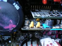
Also two operational (one of them quite difficult to access, see photo)
U3 TL072 (near RCAs)
pin 4: -13.70 V
pin 8: 12.24 V
TL072 (the one below in the photo, which is barely visible) (U. ...?)
pin 4: 0V
pin 8: 12.25 V
Should I keep track of the pin 4 volts should be negative?
Any ideas? (What good would the scheme ....) (I'm looking for ...)
I have some tensions:
U1000 regulator (LM317)
Adj: 12.64 V
Vin: 23.11 V
Vout: 13.89 V
U1001 regulator (LM337)
Adj: -14.08 V
Vin: -22.17 V
Vout: -15.36 V
These measures, are they correct? (I think so ...)
Also two operational (one of them quite difficult to access, see photo)
U3 TL072 (near RCAs)
pin 4: -13.70 V
pin 8: 12.24 V
TL072 (the one below in the photo, which is barely visible) (U. ...?)
pin 4: 0V
pin 8: 12.25 V
Should I keep track of the pin 4 volts should be negative?
Any ideas? (What good would the scheme ....) (I'm looking for ...)
Attachments
Yes, the pin4 of the op-amp, it reads 0 on the speaker terminals ...
Well, it seems I've been lucky ...
I continued checking components, and thinking, thinking, there has been a moment when he connected (with the meter on the terminals of the speaker) that occurred to me, pressing down on C1015, and have disappeared 66V !! leaving only 0.052 V!!
So, I returned to tin, again the three capacitors, and C1001, 1002,1003,1004,1005,1008 (because I was suspicious of their welds)
I connected the speaker, audio input, and sing! for half an hour without any problem.
This I found strange, if you know think that this is a difficult amplifier, or to save on costs, have spared tin ¿? Will there be manufactured in China?
What do you think, Perry?
Anyway, I will not tire, to thank Perry for his help.
I applied for the scheme in two places, and do not know if I send it, if they do not hesitate to send your mail, Perry.
A greeting.
Bad news, I again have problems with this amp ....
The amplifier had been working when I left it (in June) since then, until now, has been in the closet, without connecting.
Now I want to install it on my car, and yesterday, I decided to try it, (because I did not trust)
It is rare ....
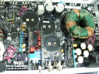
When connected, output from the speaker terminals, 50 to 63 volts, but when I press down on a point on the motherboard (see photo) with a pencil "disappear" leaving only, 0.056 volts ... ..
I have reviewed tin solder near the point, without success ...
I replaced the three capacitors power supply ... (previous capacitors were swollen), could it be that the swell, push the lid and turn the motherboard, causing a cut on her?
Could be a leaky transistor?
The fact is, that when it starts to run (0.056 v) and then continues to run smoothly, but if we give a tap on the area, stops working ...
I do not know, I do not know .... I have lost .... I think so many things that could be ....
And I can not find the wiring diagram .... ggrrrrrr,,,,,
Keep looking .....
Any help is appreciated.
The amplifier had been working when I left it (in June) since then, until now, has been in the closet, without connecting.
Now I want to install it on my car, and yesterday, I decided to try it, (because I did not trust)
It is rare ....
When connected, output from the speaker terminals, 50 to 63 volts, but when I press down on a point on the motherboard (see photo) with a pencil "disappear" leaving only, 0.056 volts ... ..
I have reviewed tin solder near the point, without success ...
I replaced the three capacitors power supply ... (previous capacitors were swollen), could it be that the swell, push the lid and turn the motherboard, causing a cut on her?
Could be a leaky transistor?
The fact is, that when it starts to run (0.056 v) and then continues to run smoothly, but if we give a tap on the area, stops working ...
I do not know, I do not know .... I have lost .... I think so many things that could be ....
And I can not find the wiring diagram .... ggrrrrrr,,,,,
Keep looking .....
Any help is appreciated.
Attachments
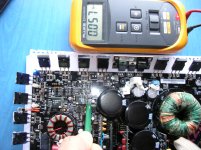
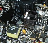
The solder connections on the 4 large SMD transistors in this area fail. For testing, you can sometimes simply solder the connections in place. To make it reliable, the transistors need to be removed, the pads cleaned on the board and the terminals cleaned on the transistors.
Sometimes these transistors become intermittent. I've had at least one that checked bad in the board (open B-E junction) but checked OK out of the board so I'd advise checking them in the board as well as out of the board.
If they're readily available, I'd advise replacing them.
I've substituted TO-220 transistors in a few amps but haven't done enough to know if it's 100% reliable (although it should be). I've used 2N6488s and 2N6491s. The transistor shown is a 2N6491. The rest are NPN and would be subbed with the 2N6488 if necessary.
Attachments
- Status
- This old topic is closed. If you want to reopen this topic, contact a moderator using the "Report Post" button.
- Home
- General Interest
- Car Audio
- Rockford Fosgate T1500-1 BD