I used to run these amplifiers when I competed several years ago. The other day while at the pawn shop I picked one up for an awesome price and have been trying to clean it up inside and out as best I can. Now when I competed I remember there was some sort of mod done to these amps by earthquake but I can't remember for the life of me what it was. It was done to several of my amps and I think it had something to do with making the amp more stable into low impedance loads. I remember at one point an earthquake tech soldering some additional caps in the amplifier(i believe they were rail caps). I see a spot on the board where two more caps could be added but I am not sure if i should even mess with it. I was hoping somebody here maybe knew of this mod and if it was feasible/worthwhile.
Last edited:
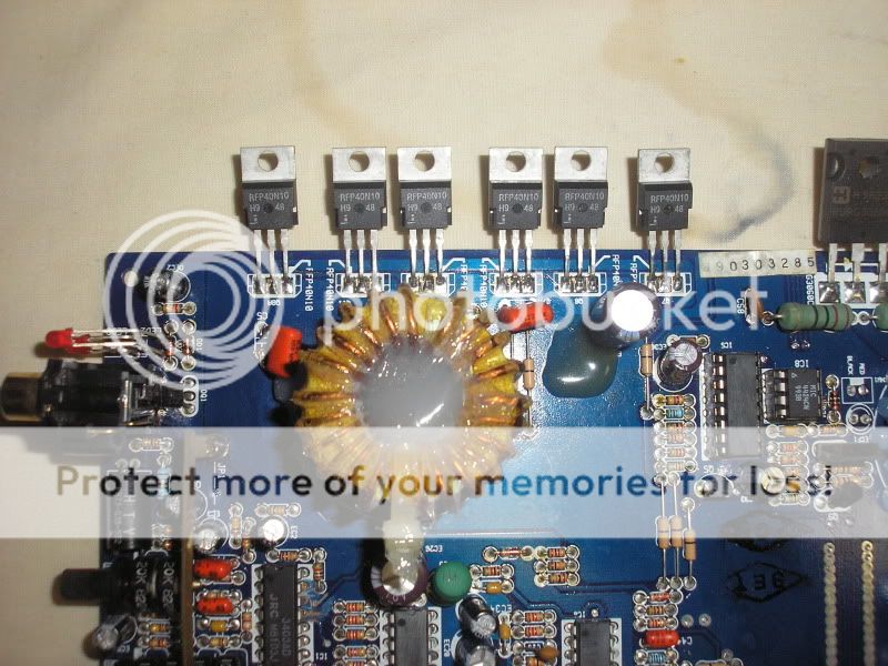
i've had some people on another forum suggest that earthquake swapped the usual fets for higher rated fets when this mod was done. They said something along the lines of swapping the outputs from rfp40n10's to 50n10's and 80n10's in the power supply for 100n10's. Not sure if they also changed the gate resistors when this was done. They also gave me a pic of an ic with diodes piggy backed onto it. Does this sound like it would even accomplish anything
I've seen the zeners soldered on the IC. I think it was done to protect the FETs (and possibly the IC) in case an output shorted to ground. I don't think it was needed on the amps that had the Zener diodes connected directly across the gate/source of the outputs.
More capacitance would likely only help. I saw a couple of MMATS amps with large caps outside the case. This was supposedly a mod for those who wanted to run them into lower ohm loads.
What are the gate resistors on the outputs in your amp?
Does your amp have two diodes and a gate resistor directly in front of the outputs?
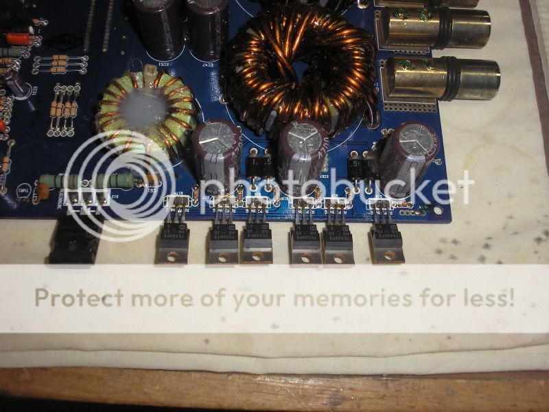
Gate resistors on the outputs are 100 ohms. It looks like one gate resistor feeds 3 output fets. I only found 4 gate resistors and they are mounted closer to the center of the amp along with some zeners. There is no diodes and gate resistors directly in front of the outputs. There is some large diodes in front of the ps fets along with the gate resistors. How much capacitance should i add to the rails. It currently has 4 100v 470 microfarad caps and there is room for two more unless i just add some larger ones laying on their side. If i do add some i will probably change them all so they match.
Yours may benefit by adding the diodes on the IC. I don't know how easy it would be to change the outputs without further mods. The amp should be relatively reliable if you don't try to run it below its lowest rated impedance.
Did the person that sent you the photo of the diodes (on the IC) give you the part number for the diodes?
Did the person that sent you the photo of the diodes (on the IC) give you the part number for the diodes?
No I didn't get a part number on those diodes but I can ask to see if maybe they know what they are. If I can find out the part number I will add those diodes and not worry about touching the outputs. I can't think of when I would need more power than this amp is capable of at 2 ohms anyhow. What are your thoughts on adding the rail caps Perry? Also curious if you knew whether or not I was correct in my assumption that one gate resistor was attached to the gate on three of the 12 output fets?
If this was my amp, I wouldn't add any capacitance. If I were to add two more caps, I'd replace the ones that were already there so all of the caps would match and the workload would be shared equally.
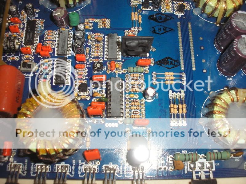
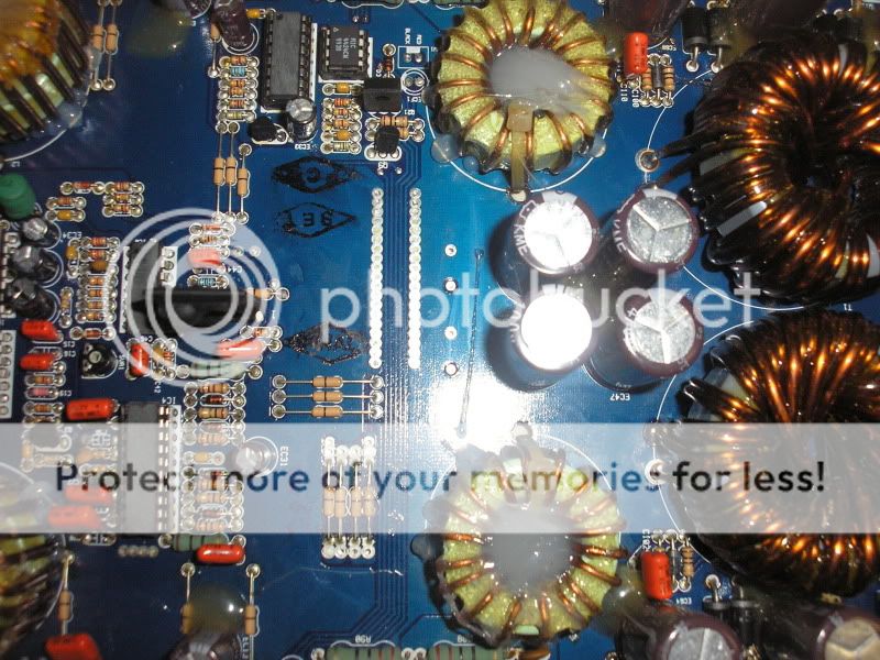
If it's the version I think it is, it has one resistor and one diode per 3 FETs. All of them are near the HIP4080.
If it's the version I think it is, it has one resistor and one diode per 3 FETs. All of them are near the HIP4080.
If it's the version I think it is, it has one resistor and one diode per 3 FETs. All of them are near the HIP4080.
This is exactly how mine is assuming the HIP4080 is the chip that people are putting those zeners on. Numbers have been ground off of several of the IC's of course so its impossible to tell which one is which other than basing it off of the location of other components. I'll leave the rail caps as is. No need to buy additional parts if there isn't anything wrong with the amp.
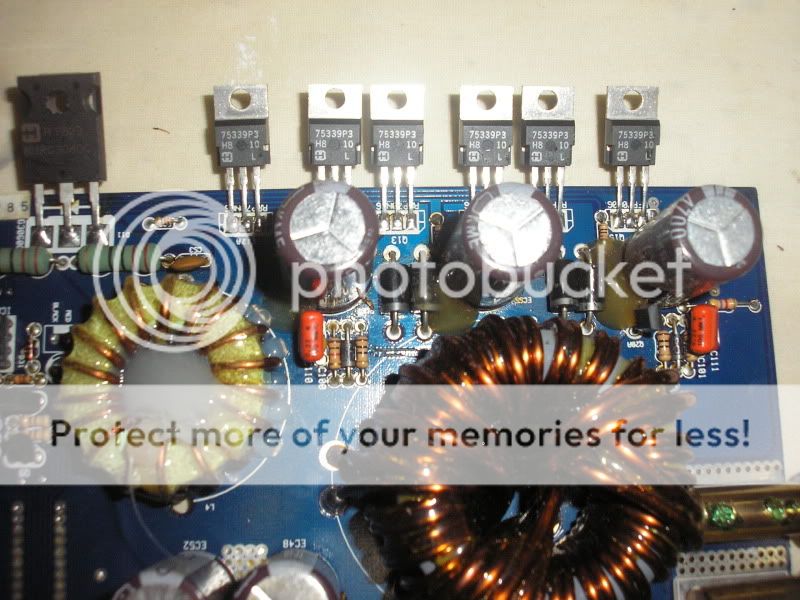
I assume you are talking about the diodes next to the power supply fets(clarification please). If so I can open mine up and get the part number for you if somebody else doesn't already know it. As far as the fried fet unfortunately you are gonna have to replace all of the fets in parallel with it and hopefully you don't have blown power supply fets because of blown fets in the output section. Also if the power supply fets are blown you will need to check the gate resistors to make sure they are within tolerance.
We need to clarify what model you are working on as well.(d200hc,phd2,d200hc mark 2?)
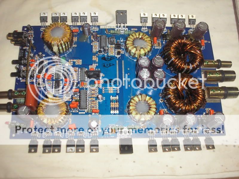
I will upload a photo as would be a better way to clarify. It is a PHD2 (SHREDDER) as i beleive.
Hi guys, Having major problems uploading image, so heres one to download, lol thx for the quick reply.
17032010569.jpg
17032010569.jpg
Hi thank you, here is a link..Modding an Earthquake Power House PHD2 Shredder | Decibelcar.com the SPL & Decibel Car Audio KnowledgebaseWhere did you get this list of modifications?
The diode appears to be a 1.5KE36A.
Thats an awesome link xmikee. It appears to have the info I was originally trying to track down when I started this thread although I think they have it wrong when they say the diodes are across pins 18 and 20 and pins 4 and 2 . Based on the position of the clock mark I don't believe those are the correct pins. I think it looks to be pins 11 and 12 and pins 19 and 20
Last edited:
Glad to helpThats an awesome link xmikee. It appears to have the info I was originally trying to track down when I started this thread although I think they have it wrong when they say the diodes are across pins 18 and 20 and pins 4 and 2 . Based on the position of the clock mark I don't believe those are the correct pins. I think it looks to be pins 11 and 12 and pins 19 and 20
") I am a complete novice with basic skills, So what do you think, do this mod. One thing is on the link diagrm it shows Replace R37 with 73kohm, But on the description is says replace R37 with 75kohm My diagram i posted any feedback of what i should do. ie questions ideas, want to get it running again. I have 2 orion HCCA 15.2. just sitting there doing nothing. want to get sorted. thx
I am a complete novice with basic skills, So what do you think, do this mod. One thing is on the link diagrm it shows Replace R37 with 73kohm, But on the description is says replace R37 with 75kohm My diagram i posted any feedback of what i should do. ie questions ideas, want to get it running again. I have 2 orion HCCA 15.2. just sitting there doing nothing. want to get sorted. thx
Last edited:
- Status
- This old topic is closed. If you want to reopen this topic, contact a moderator using the "Report Post" button.
- Home
- General Interest
- Car Audio
- Earthquake D200hc/phd2 modification?