Hello from Italy
Help me please with the schematic/data sheet at Phoenix Gold ms 2125
My e-mail address lokatos@tiscali.it
Thanks in advance to all !!!
Help me please with the schematic/data sheet at Phoenix Gold ms 2125
My e-mail address lokatos@tiscali.it
Thanks in advance to all !!!
Help on MS2125 and MS275
Hi,
I owned both amps, and the filter caps after the choke blow(2200uf/16V) on MS2125 and the caps leaked on MS275 and after I can the caps, the amp have no sound on MS275 and MS2125 have distortion sound on the right channel where the filter caps blow. Please please send me the schematic on both amp if you have them. Your help is much appreciate. Thank in advance.
Viwat from Bangkok, Thailand.
viwats@hotmail.com
Leaking caps on this old of a series of car amps ~15 years+ is not uncommon. Replacement is standard and should save the board and restore proper operation to the power supply.
The issue of distorted or no sound is caused by other issues in the defective channels. The 275 has a single power supply unlike the 2125 which has two supplies one for each channel. So the logic that the 12 volt filter caps are causing the channel issue do not connect, except on the 275 please see below.
PG uses flame proof fuse type resistors on every stage after the diff input pairs. You should start by reading these and making sure these are to spec, and not open. Look for the green or Grey body colored 1/4 watt resistors in the circuitry. There will be one of the same value on each polar side of the amp all the way up to the outputs transistors. These were designed in to prevent catastrophic failures.
If these are all good then your most likely looking for other out of value components in the circuit. But these resistors are typically the safety failing devices that go before any other damage usually can occur. If one has opened up then check both forward and back of the open resistor for bad transistors.
Also take a small computer motherboard battery and test each of the two red LEDs located in each channel. These also blow open and when they do they of course do not light up anymore and the inter-stage pathway is now broken in that channel. The LED has been chosen for its specific voltage drop so try to match up a exact replacement device based on voltage drop in circuit.
By chance did you check the output terminals for DC Offset voltage prior to sound testing the amp ? If not then please test for DC output with no RCAs connected and no speakers connected and the amp idling turned on.
Also understand that the 275 may not be producing sound because the power supply may have safety off after turn on, thus muting the amp because their is something else severely wrong in the amp causing the supply to shut down. A simple idle current draw test will tell you if the amp has done a fault safety shut down.
On the MS-275 I have also seen the 12 volt caps after being replaced by a novice cause the amp to not turn on. This is because PG used doubled sided boards and the ground from one side of the board to the other lost its connection during cap replacement because of thru hole pull out. This will require that the board layers be reconnected by hard wire thru the damaged thru hole for the cap lead that was damaged. This happens a lot more then you would think, it even happened to me once...

I have seen the LM339 go defective. This is the safety sense amp device. The amp should be idling under 1.5 amps and typically just under 1 amp. This all depends on how high the channel bias is set. But the lowest operating idle current will be about 0.6 to 0.7 amperes. Also the 35 volt rails will be on and balanced if the supplies are operating correctly. This can be checked at the fuses just after the large rail caps. In the 4 ohm mode you should get about 35 volts to RCA ground from each fuse, in the 2 ohm mode this drops about 10 volts to around 25 or 26 volts typically.
Once the supply is tech'ed out and operating then you should be able to tech out the channels by first reading the DC offset as a clue to where the damaged channel is first.
PG was recently sold off to Stinger/AAMP. They still service these amps even today. Unfortunately this service is only here in the US. PG to my knowledge has never released any schematics on their top line products like the ones you have....hope this helps some I pretty much covered all the basics for you...
I emailed Lakatos the exact info he needed for his issues down to part numbers and such and part ID on the board. If you find your issues I can do the same. You are still at the beginning by your post. Follow what I posted and you will have enough info for me to guide you the rest of the way.....C
Last edited:
anyone can send me schematic / service manual for MS275?
calvinhpk@yahoo.com
calvinhpk@yahoo.com
Hello!
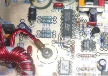
please somebody tell me what is the resistor value or r7, r8 and r11 or r10?
if somebody could send the schematic of this amp is very much appreciated. my email armand_jr2001@yahoo.com
Here is the picture of this amp.
Thank you!
please somebody tell me what is the resistor value or r7, r8 and r11 or r10?
if somebody could send the schematic of this amp is very much appreciated. my email armand_jr2001@yahoo.com
Here is the picture of this amp.
Thank you!
Attachments
- Status
- This old topic is closed. If you want to reopen this topic, contact a moderator using the "Report Post" button.
- Home
- General Interest
- Car Audio
- Help me please x Phoenix Gold ms 2125