ok,
i finally read through the "why are oldschool amps...." thread.
in that thread, i read a post, somewhere around post #395 or so, about a "front end bypass" on an amp. (i also read a post requesting a such thread to be created. i did search and did not find one in this section.)
from what i gathered, the reference was made to bypassing the input gain amps and the filtering section.
(it's been a while since i have worked this kind of stuff, so bear with me if i sound as if i am talking out of my rear...)
anyways, as an example, i have a punch 45hd that the input is bad. as a matter of fact, someone toasted the hybrid. i do know that they can still be found, but the fact that these amps can still be found cheap, causes my interest in restoring it to "factory" condition does not excite me.
now, if i understood correctly, the op amps of the "preamp" section were mainly used to drive the amp section because the line level max of the head units at the time were running up to a max of 2 volts?
if i read correctly, newer head units are running up to 5 volts?
is this correct?
in any case, looking at the schematic of the 45hd, and based on what i have gathered so far, i should be able to use a current head unit and run the line outs into the rca's jumped straight to c9 and c10. the ground appears to be common.
any comments?
thanks!
You need isolation from the chassis ground on the inputs to prevent having a ground loop. Send me a copy of the schematic and I'll try to determine if it will work with no input board.
babin_perry@yahoo.com
babin_perry@yahoo.com
I'm not certain about this because of the limited information available so it may not be correct and may cause damage...
It 'appears' that the differential input to the hybrid audio driver board uses pins 1 and 3. Pin 1 is connected to ground on both boards.
If you cut the trace connecting pin 1 to ground and connect that pin to the shield ground of the RCA signal line, it 'should' work. You'd feed signal into pin 3. You may need to connect a resistor (4.7k-10k) between pin 1 and ground to make the amp stable when there are no RCAs plugged in. Wired this way, the right channel speaker would have to be wired backwards. If you get this working with no engine noise, it should be easy to re-wire the inputs to get the amp bridgeable again.
perry, the hybrid board on the 45hd is the same as the punch 45 preamp section as seen below, but pretty much everything up to the immediate circuit of both halves of the tl072 less r113 on the non hd drawing.
on the hd, the input caps are 10uf versus 1u on the punch 45.
also, on the hd, (the amp in question), it appears that the input signal ground is tied to the power ground.
on the original punch series, it appears the input signal ground is connected to power ground via r114 and r214.
on the hd, the input caps are 10uf versus 1u on the punch 45.
also, on the hd, (the amp in question), it appears that the input signal ground is tied to the power ground.
on the original punch series, it appears the input signal ground is connected to power ground via r114 and r214.
Attachments
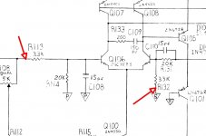
The points indicated by the arrows are the connection points for the signal and shield. The 'S' ground is the one you have to break from pin 1 of the driver board.
R113 is probably in the circuit. The resistors are the black rectangles on the back of the board.
R113 is probably in the circuit. The resistors are the black rectangles on the back of the board.
Attachments
The points indicated by the arrows are the connection points for the signal and shield. The 'S' ground is the one you have to break from pin 1 of the driver board.
R113 is probably in the circuit. The resistors are the black rectangles on the back of the board.
thanks perry. i might look at that some more this weekend on the bench with the scope and a test deck.
you sure the resistors aren't the red stop sign looking thingys? ..... lol
just kidding, i am familiar with what components physically look like.

- Status
- This old topic is closed. If you want to reopen this topic, contact a moderator using the "Report Post" button.
- Home
- General Interest
- Car Audio
- amplifier "front end bypass"