I noticed most separate component speakers say they are 4 ohm speakers. But that's connected to the crossover and both speakers connected to the crossover.
What is the impedance of the tweeter and mid separate? Would that make each of them 2 ohm run in parallel or 8 ohm in series? Or does the passive crossover do some magic and the speakers are really 4 ohm each?
What is the impedance of the tweeter and mid separate? Would that make each of them 2 ohm run in parallel or 8 ohm in series? Or does the passive crossover do some magic and the speakers are really 4 ohm each?

4 ohms each. The crossover isn't magic, it's purely physics. Mostly Ohm's Law.
Internally, a two-way M/T crossover will have separate crossovers for the midrange and tweeter. The inputs to the individual sections are tied together in parallel.
Let's look at a simple first order (6dB) HP tweeter crossover:
It's just a capacitor in series with the tweeter...
The value of the capacitor is chosen so that it presents an impedance (Xc) equal to the tweeter's at the desired crossover (-3dB) frequency. Here's the formula: C=1/(2*pi*f*Xc)
Let's say the tweeter is indeed 4 ohms, and you want to crossover at 4000 Hz.
C=1/(2*3.14*4000Hz*4ohms) = 0.00000995 Farads or 9.95uF
Now, lets look at what's happening with a 4000 Hz sine wave running through that system... You have a 4 ohm speaker in series with a 4 ohm capacitor. So that's an 8 ohm load at 4kHz as far as the amp is concerned. The tweeter is only "getting" half (4/8) of the crossover's input voltage, and output would be 3 dB less than it would be without the capacitor.
Turn the equation around to find the capacitor's impedance (actually called reactance) at 8000 Hz:
Xc=1/(2*3.14*f*C)
Xc = 1/(2*3.14*8000Hz*9.95e-6uF) = 2 ohms
So, at 8kHz the capacitor is 2 ohms. The cap and tweeter in series present a 6 ohm load to the amp, and the tweeter "gets" (4/6) 2/3 of the crossover's input voltage, more than half. The capacitor's reactance continues to fall until it is effectively out of circuit.
OK, let's go down below the crossover f3 to 2000Hz and see what's happening.
Again, Xc=1/(2*3.14*2000Hz*9.95e-6) = 8 ohms
So the capacitor is 8 ohms at 2kHz. The cap and tweeter in series present a 12 ohm load to the amp, and the tweeter "gets" (4/12) only one third of the crossover's input voltage. The capacitor's reactance increases as frequency goes down until the tweeter is effectively out of circuit.
Exactly the opposite happens in the low pass circuit, and the two circuits in parallel are a reasonable equivalent to the load of the individual speakers in the region where they are effectively working.
Higher order crossovers simply add more components to increase the rate that the output voltage changes with frequency.
Hope that helps.
Hi
The crossover circuit helps define the range of frequencies for each driver and outside that range, the specific drivers impedance will rise due to the crossover, so as not to load each other too much in parallel. So generally the midbass impedance will rise due to added series inductance and the tweeter impedance will rise due to series capacitance. So the net impedance seen by the amp at the crossovers input is kept around the range of 3-6 ohms. Is that clear as mud?
The crossover circuit helps define the range of frequencies for each driver and outside that range, the specific drivers impedance will rise due to the crossover, so as not to load each other too much in parallel. So generally the midbass impedance will rise due to added series inductance and the tweeter impedance will rise due to series capacitance. So the net impedance seen by the amp at the crossovers input is kept around the range of 3-6 ohms. Is that clear as mud?
wpc said:Wait, are you saying that each are 4 ohms but the impedance presented to the amp is even higher than 8 ohms because of the crossover?
If you are considering just the woofer or just the tweeter with it's crossover section, yes it can be.
To make matters even more counter-intuitive, the individual speaker's impedance (without the crossover) will also rise above 8 ohms as frequency rises. Impedance, by definition, isn't constant.
if you are building a 4ohm speaker then select 4ohm drivers and select a crossover for 4ohm drivers.
If you mix driver impedances by choosing an 8ohm and a 4ohm driver or by paralleling a pair of 8ohm drivers and a single 8ohm driver then your crossover becomes more complicated. Each half of the crossover must be designed for the load that you attach to it.
If you mix driver impedances by choosing an 8ohm and a 4ohm driver or by paralleling a pair of 8ohm drivers and a single 8ohm driver then your crossover becomes more complicated. Each half of the crossover must be designed for the load that you attach to it.
4 ohms each. The crossover isn't magic, it's purely physics. Mostly Ohm's Law.
Internally, a two-way M/T crossover will have separate crossovers for the midrange and tweeter. The inputs to the individual sections are tied together in parallel.
Let's look at a simple first order (6dB) HP tweeter crossover:
It's just a capacitor in series with the tweeter...
The value of the capacitor is chosen so that it presents an impedance (Xc) equal to the tweeter's at the desired crossover (-3dB) frequency. Here's the formula: C=1/(2*pi*f*Xc)
Let's say the tweeter is indeed 4 ohms, and you want to crossover at 4000 Hz.
C=1/(2*3.14*4000Hz*4ohms) = 0.00000995 Farads or 9.95uF
Now, lets look at what's happening with a 4000 Hz sine wave running through that system... You have a 4 ohm speaker in series with a 4 ohm capacitor. So that's an 8 ohm load at 4kHz as far as the amp is concerned. The tweeter is only "getting" half (4/8) of the crossover's input voltage, and output would be 3 dB less than it would be without the capacitor.
Turn the equation around to find the capacitor's impedance (actually called reactance) at 8000 Hz:
Xc=1/(2*3.14*f*C)
Xc = 1/(2*3.14*8000Hz*9.95e-6uF) = 2 ohms
So, at 8kHz the capacitor is 2 ohms. The cap and tweeter in series present a 6 ohm load to the amp, and the tweeter "gets" (4/6) 2/3 of the crossover's input voltage, more than half. The capacitor's reactance continues to fall until it is effectively out of circuit.
OK, let's go down below the crossover f3 to 2000Hz and see what's happening.
Again, Xc=1/(2*3.14*2000Hz*9.95e-6) = 8 ohms
So the capacitor is 8 ohms at 2kHz. The cap and tweeter in series present a 12 ohm load to the amp, and the tweeter "gets" (4/12) only one third of the crossover's input voltage. The capacitor's reactance increases as frequency goes down until the tweeter is effectively out of circuit.
Exactly the opposite happens in the low pass circuit, and the two circuits in parallel are a reasonable equivalent to the load of the individual speakers in the region where they are effectively working.
Higher order crossovers simply add more components to increase the rate that the output voltage changes with frequency.
Hope that helps.
not to hijack a thread but i can't find a straight answer on this. i see a lot of people installing a tweeter in parallel with a midbass speaker, using "bass blockers" (capacitors) in series between the tweeter and mid bass. both speakers are 4 ohm. my question is, since the mid bass does not have a crossover on it, wouldn't the impedance of that "component" setup produce some odd values at frequencies above the bass blocker? trying to determine the what impedance the amp would see for wattage calculations. thanks in advance for your response.
Speaker impedances are always at odd values, it changes with frequency.
I know it's hard to do so, but let go of the notion that a speaker is either 4 ohms, or 8 ohms, etc. It's dynamic, and the impedance will change with frequency. That's why you're not getting a "straight" answer. The beginning of a straight answer is buried in that long winded, boring post post you quoted. Impedance and power calculations are much more involved than a single number.
Assuming the numbers quoted above are accurate, think about the 2000 Hz example. The tweeter + capacitor have a combined impedance of 12 ohms, right? Your midbass has an impedance of "4 ohms", so the parallel combination *should* present a 3 ohm load to the amp. I think that's the straight answer you're looking for, but it's not that simple...
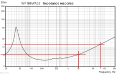
Look at the impedance plot below. This is a typical midbass driver impedance plot. Look at the impedance at 2000 Hz. It's not 4 ohms, it's more like 5½ ohms there. So, with this driver, we're now looking like 12 ohms in parallel with 5½ ohms, which is ~3.77 ohms.
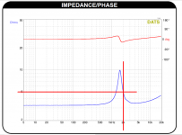
But wait, we're not done... the tweeter has a similar impedance curve... again, here's a typical impedance plot for a 1" or so dome. We were looking at 2000 Hz, so looking there, the tweeter is 5 ohms at that point. OK, so now it's 5 ohms in series with the cap that's 8 ohms, for a series total of 13 ohms, which is in parallel with the 5½ ohm woofer impedance. Net impedance to the amp is still going to be just under 4 ohms, but you see that all of these values are constantly changing.
You mentioned frequencies above the bass blocker... Go up to 8kHz and the cap is 2 ohms, the tweeter is about 3.75, but the woofer is about 12 ohms. Net result is around 3.9 ohms there. The good thing is these values tend to move in opposite directions and the result can be reasonably consistent.
So the point of this long winded answer is to yes, this produces odd impedance values, but that's totally normal in the world of audio. If the speaker manufacturer or distributor provides data files, you should be able to load them into a simulator and get accurate Z plots to see the changes graphically.
I know it's hard to do so, but let go of the notion that a speaker is either 4 ohms, or 8 ohms, etc. It's dynamic, and the impedance will change with frequency. That's why you're not getting a "straight" answer. The beginning of a straight answer is buried in that long winded, boring post post you quoted. Impedance and power calculations are much more involved than a single number.
Assuming the numbers quoted above are accurate, think about the 2000 Hz example. The tweeter + capacitor have a combined impedance of 12 ohms, right? Your midbass has an impedance of "4 ohms", so the parallel combination *should* present a 3 ohm load to the amp. I think that's the straight answer you're looking for, but it's not that simple...
Look at the impedance plot below. This is a typical midbass driver impedance plot. Look at the impedance at 2000 Hz. It's not 4 ohms, it's more like 5½ ohms there. So, with this driver, we're now looking like 12 ohms in parallel with 5½ ohms, which is ~3.77 ohms.
But wait, we're not done... the tweeter has a similar impedance curve... again, here's a typical impedance plot for a 1" or so dome. We were looking at 2000 Hz, so looking there, the tweeter is 5 ohms at that point. OK, so now it's 5 ohms in series with the cap that's 8 ohms, for a series total of 13 ohms, which is in parallel with the 5½ ohm woofer impedance. Net impedance to the amp is still going to be just under 4 ohms, but you see that all of these values are constantly changing.
You mentioned frequencies above the bass blocker... Go up to 8kHz and the cap is 2 ohms, the tweeter is about 3.75, but the woofer is about 12 ohms. Net result is around 3.9 ohms there. The good thing is these values tend to move in opposite directions and the result can be reasonably consistent.
So the point of this long winded answer is to yes, this produces odd impedance values, but that's totally normal in the world of audio. If the speaker manufacturer or distributor provides data files, you should be able to load them into a simulator and get accurate Z plots to see the changes graphically.
Attachments
Last edited:
Oh ok. That makes sense. What I was trying to figure out is if it would seem like the higher frequencies would be perceived as being much louder than the mid. Based on what you are saying, it seems like they would be which makes sense. To put it bluntly and massively over simplified edging on being incorrect, the case I was trying to consider is something like:
120hz tone:
Full channel power to 4 ohm full range mid
“0” power to 4 ohm tweeter (no sound)
8000hz tone: (assuming 2 ohm stable channel)
Full channel power to 4 ohm full range mid
Full channel power to 4 ohm tweeter
To me this would create an imbalance with a lot of highs coming through. Solved by a SP, but nonetheless an imbalance.
- Status
- This old topic is closed. If you want to reopen this topic, contact a moderator using the "Report Post" button.
- Home
- General Interest
- Car Audio
- Component speakers and Impedance values