When I first got this amplifier it had blown output transistors,
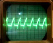
I leaved just 2 working in place and tested the amplifier shortly, it worked. But when I put the new output transistor in place they blew again,now I again put 2 working transistors in place, and found out that at least lower side mosfet was getting some kind of sawtooth waveform.
Now I am afraid of powering it up to measure so I would hope that you can point me to right direction. I have a basic car audio repair tutorial, but I can't find help from it.
Try the following file in the 81000D folder. The waveforms should be very similar.
repair_tutorial\miscellaneousstuff\mtx\mtx81000d\mtx81000dwaveforms04.swf
The mtx81000dwaveformsandnotes.htm file in the 81000D file should also be helpful.
Have you checked the gate resistors for each of the outputs?
Did LED 238 light up before they blew?
Did you use the exact replacement parts for the outputs?
Where the 2 that you left in place the originals or were they the same as the ones you used as replacements?
Some of these amplifiers will not work properly with the new replacements. If you cannot find any defective components and the amp continues to blow the outputs, you may have to increase the resistance of the 2 large resistors near the opto-couplers.
One gate resistor is open, but in there is no fet. Im not sure was it ok before.
It took long time for transistors to arive.
Im not sure what led do you mean, there is led 463 and 399 but i think they bouth ligh up, at some point.
exact IRFB42N20D
I leaved 2 in place so they are the new ones.
But what I really doesnt understand is how can gate singnal to lower side mosfet in waveforms be less than 5vpp
Waveform from my amps lower side mosfets gate AC about 5Vdiv
Attachments
LED238 is near the board mounting screw that's closest to the opto-couplers. If it's not coming on, and you have a drive signal, it may be defective.
LED463 is the power LED and should be on when remote voltage is applied. LED399 (in-between large caps?) tells you that the caps are charged (a warning t be careful).
If your scope was set to 5v/div, it appears that you have a 10v-peak signal (not including the spike below the rail).
Did you have an FET in the location where there is an open gate resistor? If so, that could have caused the new FETs to blow.
The amplitude of the waveform isn't significant at idle. The amp's servo/feedback circuit changes the pulse width to maintain 0v DC on the output at idle. Since the pulse width determines the amplitude on the gate (due to the charging of the gate capacitance), the actual peak gate voltage will vary.
From the information you provided, I'd feel confident in replacing the output and resistor and applying power. If the over-current protection is working properly and the outputs are clamped to the sink, the amp should go into protection if there is a problem.
If it powers up normally and the audio section oscillates properly (as it seems to be doing now), drive a signal into it and drive the output to clipping with no load. If LED238 doesn't blink off, connect a load and run it at increasingly high output. If LED238 remains on at full power, the amp will probably be OK.
If it powers up normally and the audio section oscillates properly (as it seems to be doing now), drive a signal into it and drive the output to clipping with no load. If LED238 doesn't blink off, connect a load and run it at increasingly high output. If LED238 remains on at full power, the amp will probably be OK.
 )
)There are two large resistors near the HCPL3120s. They are probably marked 1000 (100 ohms). I've had to increase these to 300 ohms in several amps to get them to function properly with the new FETs.
You want to use the lowest value possible but it will have to be greater than 100 ohms. Of course, this assumes that all of the gate resistors are within tolerance, the diodes adjacent to the large resistors are intact and the HCPL3120 are working properly.
You want to use the lowest value possible but it will have to be greater than 100 ohms. Of course, this assumes that all of the gate resistors are within tolerance, the diodes adjacent to the large resistors are intact and the HCPL3120 are working properly.
First I did measure diodes otherwise OK, but they did measure about 1,5Mohm reversed, using fluke multimeter, other end was disconnected. Diode mode was OK, so I think they were alright?
But when I try to measure output waveform, It looks like dimming sinewave, end of oscillation?
And I started to think that my O-skope might be loading circuit too much.
I repaired other amp Blaupunkt velocity WD-504 it works fine but when I try to measure output waveform the chancel shuts down.
How could I know if O-skope is broken? Callibration output produces good signal, but it is only 1KHz.
I think the diodes are OK. I found reverse leakage on all that I've checked.
If you mean that the oscillation looks like a sine wave with decreasing amplitude, I've also seen that but it's generally only when there is no signal and no load. Generally, when you drive a signal into the amp and there's a load on it, the oscillation becomes square.
If you touch the tip of your scope probe to the speaker terminal of an amplifier that's driving a speaker (producing normal audio) and it causes the amp to shut down, the scope probe is probably defective. Most scope probes are 10:1 and have a 9M ohm resistor in the probe body. This would prevent the scope's input circuit from loading the amp. If you have a 1:1 probe, the scope could be loading the amp down but the wires in the probe are generally so tiny that they would burn before they would shut down an amp.
Insert a 100 ohm resistor betwen the tip of the scope probe and the device being tested. If the readings are essentially the same with/without the resistor, the scope probe is OK.
With input signal and speaker connected amp produces sound, but it also produces weird hi-frequency noise.
Output waveform is kind of square wave and sine wave with decreasing amplitude. Maybe, first square wave and then sine wave amplitude decreasing then square wave again.
Output waveform is kind of square wave and sine wave with decreasing amplitude. Maybe, first square wave and then sine wave amplitude decreasing then square wave again.
Is the noise produced by the speaker or by components in the amp?
The square wave on the outputs will change significantly. It may not always be square on all amps until it's driven hard. Even then it may not be a perfect square wave.
Is anything in the amp (output filter caps, output transistors...) running hot?
The square wave on the outputs will change significantly. It may not always be square on all amps until it's driven hard. Even then it may not be a perfect square wave.
Is anything in the amp (output filter caps, output transistors...) running hot?
- Status
- This old topic is closed. If you want to reopen this topic, contact a moderator using the "Report Post" button.
- Home
- General Interest
- Car Audio
- mtx 1501d sawtooth waveform