I'm on a mission to find the output stage schematics diagram for a PG Titanium 500.4.
My repairer is just about finished replacing the burnt components but there are a few fine traces on the board he cannot trace to a location due to the burnt board.
Please help me help him. Thanks in advance.
My repairer is just about finished replacing the burnt components but there are a few fine traces on the board he cannot trace to a location due to the burnt board.
Please help me help him. Thanks in advance.
I don't have the schematic but he shouldn't need one on a 4 channel amp. Generally, when someone lays out a board, they produce one channel and copy/paste the rest of the channels. If they're not an exact copy, they will be a mirror image. Either way, it shouldn't be difficult to trace the circuits.
Could you post a pic of the area you need? I have two working 500.4's on my bench.
Plus I must admit, I have never seen a burnt board on these that was so bad it could not be traced easily. The Brown solder mask is opaque, but if the trace has lifted or melted its usually easily visible...PG uses fuse type resistors throughout the main amp stage of each channel to avoid such things from happening, so I am surprised that such a situation could have occurred. And I have been repairing PG since they came to market....")
Plus I must admit, I have never seen a burnt board on these that was so bad it could not be traced easily. The Brown solder mask is opaque, but if the trace has lifted or melted its usually easily visible...PG uses fuse type resistors throughout the main amp stage of each channel to avoid such things from happening, so I am surprised that such a situation could have occurred. And I have been repairing PG since they came to market....
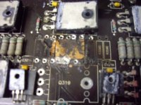
Wow! thats bad...
That section is the same as the ones beside the burnt area. It is composed of 10 each 0.51 ohm 1 watt resistors and 5 of each are paralleled to make a single large wattage Emitter resistor array for each output of that channel., times 2..of course. They may not be traced exactly the same but the circuitry is the same for all four sets of outputs for each channel.
I suggest that your tech remove the 10 one watt resistors to the left or the right of the burnt area. they will be exact circuitry of a similar layout. Just like Perry said they would be.
If the copper traces are not easily visible because of the Brown solder mask some simple ohm meter checking should show the way. E-mail me your email address so I can send you a simple layout of this section of the amp....
I can't email established members due to the restrictions on my recent membership.
However there is a solution. I have an email address that's already littered with spam so I don't mind posting here for everyone to see. I'll sift through the garbage to find your email.
Your assistance is greatly appreciated, please send it to giorgio1610@yahoo.com many thanks.
However there is a solution. I have an email address that's already littered with spam so I don't mind posting here for everyone to see. I'll sift through the garbage to find your email.
Your assistance is greatly appreciated, please send it to giorgio1610@yahoo.com many thanks.
??? did you get this amp in pieces or something???
The right angle pieces face inside the amp so the drivers can mount to it via the 4.5mm socket screws. All the other flat pieces go towards the outside back of the case.
And the higher finned TO-3 sinks get placed as they can fit on top of the plates, with the shortest located under the fan, and uneven finned ones located over the power supply section under the vent slots...
Hope this helps...Your board was badly damaged, did you drill thru so to remove any conductive pathways??
It's all good, thank for your help.
I dismantled the amp and stopped at the point where I knew I would not be able to go furhter with the repair. I packed it up (in pieces) and posted it south 539 miles interstate to the only competent repairer I could find on eastern side of Australia
All the pieces were in the box, it's just the flat plate was caught up in the bubblewrap and missed by the repairer, he has since found it all together and on its way back to me.
Thanks again.
- Status
- This old topic is closed. If you want to reopen this topic, contact a moderator using the "Report Post" button.
- Home
- General Interest
- Car Audio
- Phoenix Gold Titanium 500.4 schematics