HI
I just rewierd the power supply in the gainclone .
I went to the Brian's page and I look up the gallery . I found a similar gainclone like mine , with two transformer ect .
I saw in that gainclone the power supply was hock up diferent way like mine (after the transformer collor code), the guy who put it together he connected the power inside and the graund each side . I talk about the connection before the bridge .
Mine was reverse outside the power and inside the graund .
So I changed the connection and the amplifier now is much much better .
What a impruvment !!!!
Until now the sound was like when you listnen music from the next room .
It was mudy and with no bass at all . How I said It much better now . Now evrithing is OK just a bit I miss the butom end , tomorrow I will replace the silver wire , hopping for more impruvment .
Peter please let me know how you hock up the power supp before the diodas (bridge)
There is four connection marked AC1, AC1 - AC2 ,AC2. Now the both power is inside on the AC1-AC2 ,and much better than before .
-If I replace the panasonic capacitors to BC it will give audable impruvment or just waste of money???
About the silver wire with the teflone tube .....
I have four diferent tipe of pure silver wire and I listned before I instaled .Of course I instaled the best one and I used about 50-70 hours until now .
I spent a lot of money on silver and gold wire .
gaborbela said:HI Peter
I dont know if is OK if I post here . I purchased from your GC premium kit .I put them together using 2x20V 160VA transformer for each chanel .
I used silver wire with teflon tubing for the signal and for the power I used Kimber 4TC Kable .
It works well but unfortunatly some how I miss the bass .Compare to another amplifiers it sound les dinamic and the bass..... less punch ..
I tought to increase the power supply voltage . I purchased two toroid from same commpany but 2x25V 225VA each .
I intaled the new toroids hope to do some positive , more power or more bass but it get worst .
Yes there is more power but somehow the sound get tinier , it just get lauder with less bass .
I tried to mounth diferent film capacitors or to use larger capacitors insted the 1500MF but did no impruvment .
Do you have some idea why the larger transformers has less bass than the smaller ones .
Both from same commpany .
If you know some good idea how I can get more bass or more punch please let me know .
Thanks Regards
Ya I'm using a Alps blue velvet pot ....
I also use one of Peter's integrates. Bass has never been a problem. I get sub 20 Hz response in my room with the Audio Sector Integrated and Dac. I also use solid core silver speaker wires.
 There must be something else causing the problem.
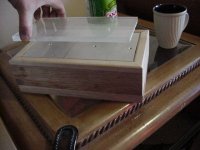
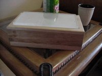
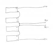
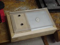
I got a premium kit awhile back and just completed an acrylic casing for it. I tried to hook up some smps units i bought for them. However, i am confused as to how to wire them properly. On the smps side, there is V+ and V-, and on the amp board side there is V-, V+ and PG's. I already blew up a chip so i want to try to be cautious. Any advice?
spacemen12 said:I've removed both ground from the amp pcb, but it didn't solve the problem. There is still a humm.
The strongest humm occurs when all the rca are connected (cd - preamp - gainclone), but only the gainclone is connected to the AC (the power cord of the preamp and cd are not plug). Then it sound like a strong ground loop. When I plug back the the power cord the noise is a lot weaker, but audible.
After removing that chassis wire you should be having a dual mono configuration without any grounds shared between channels. How long is the connection between rect board and amp's board?
The hum you are getting after switching off the sources is probably because the input to the amp is disconnected (floating) and that causes noise (and it's not recommended).
dake13 said:1) Can I build it with a switch for 110v/230V mains lines? My friend wants to be able to use it both in the US and Italy. Not sure if there's anything to watch out for with this.
2) What's a good value for a passive volume control?
3) My friend also wants Plitron trannies. It looks like I need either 067016201 (225VA, 25V output) or 077016201 (300VA, 25V output), marginal price difference. Would anyone mind confirming these parts nos. for me?
Plitron transformers with dual primaries are specified for 115/230V and 50/60Hz, so after installing swithc you can use it in Europe as well.
I like to use 25K pot.
I would go with 300VA, 25V transformer, maybe even better 2 x 22V if speaker impedance is below 8 ohms
gaborbela said:Peter please let me know how you hock up the power supp before the diodas (bridge)
There is four connection marked AC1, AC1 - AC2 ,AC2. Now the both power is inside on the AC1-AC2 ,and much better than before .
-If I replace the panasonic capacitors to BC it will give audable impruvment or just waste of money???
As I see it, there is no difference between connection to point A1 or A2, we can equally well reverse the diode pairs and marked them opposite. The orientation of wires from transformer should not be critical here.
An externally hosted image should be here but it was not working when we last tested it.
If you mean BG caps, there should be an improvement, I posted some observations here:
http://www.diyaudio.com/forums/showthread.php?postid=574431#post574431
http://www.diyaudio.com/forums/showthread.php?postid=581230#post581230
angchuck said:I got a premium kit awhile back and just completed an acrylic casing for it. I tried to hook up some smps units i bought for them. However, i am confused as to how to wire them properly. On the smps side, there is V+ and V-, and on the amp board side there is V-, V+ and PG's. I already blew up a chip so i want to try to be cautious. Any advice?
The PS connection diagram is here: http://www.audiosector.com/lm4780 psu.pdf connection to the amp is presented here: http://www.audiosector.com/lm4780 amp.pdf ( it is the same principle for LM3975 kit)
Thanks Peter
I know how to conect a transformer to the bridge ,but here we have 8 dioda per power supply and for me that new , never met before something like these .
Now I conected the +/- inside (in the midle ) in the pc board and outside the two graund .
There is a huge diference between the both conection , like totaly diferent amplifier .
May be something wrong with some dioda or I dont know .
But at least now I can use the amp.
Thanks for the help .
I will go ower on the power supp.
Cheers
I did try the wall warts on the NOS DAC.... a 12V regulated and a 12V switch mode. They both worked but the DAC lost life, slam and was not as involving.... a bit lightweight. Was a worthwhile test while building my second DAC.
End result.... stick with a normal tranny and the designed power supply.
End result.... stick with a normal tranny and the designed power supply.
Hi Peter,
I have been happily listening to my Gainclone, built from the premium kit you sold me, for about a year now. It amazes not only me but everyone who comes around and listenes to some music with me. (Some of them already built a Gainclone based on the experience.)
Now it came to my mind that I could upgrade it by changing the Panasonic caps to Black Gates as you suggest. I would have three questions:
1) How would you describe the sonic changes with the 1000 uF std + 100 uF non-polar compared to the 1000 uF Panasonic caps? Is it more natural, more transparent, more open? (on the rectifier board I presently use the small (10 uF) caps which were part of the kit)
2) In Post #997 you show a photo of the rectifier board you use. I can see there, besides the 1000 uF caps beneath the board, some small caps (? film) and some resistors (?). Do you actually use them? Or only the large caps on the rectifier and 100 uF at the amp pins?
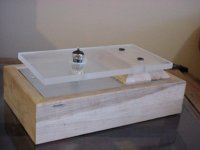
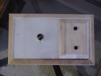
3) How big sonic difference can one make by changing the chassis material? I am thinking about some nice wood or acrillic instead of the present aluminum.
Thanks in advance.
Szabolcs
I have been happily listening to my Gainclone, built from the premium kit you sold me, for about a year now. It amazes not only me but everyone who comes around and listenes to some music with me. (Some of them already built a Gainclone based on the experience.)
Now it came to my mind that I could upgrade it by changing the Panasonic caps to Black Gates as you suggest. I would have three questions:
1) How would you describe the sonic changes with the 1000 uF std + 100 uF non-polar compared to the 1000 uF Panasonic caps? Is it more natural, more transparent, more open? (on the rectifier board I presently use the small (10 uF) caps which were part of the kit)
2) In Post #997 you show a photo of the rectifier board you use. I can see there, besides the 1000 uF caps beneath the board, some small caps (? film) and some resistors (?). Do you actually use them? Or only the large caps on the rectifier and 100 uF at the amp pins?
3) How big sonic difference can one make by changing the chassis material? I am thinking about some nice wood or acrillic instead of the present aluminum.
Thanks in advance.
Szabolcs
I'm certainly familiar with your listening impressions as they are quoted on my website ")
Here, I described my impressons, when listening to different capacitor types:
http://www.diyaudio.com/forums/showthread.php?postid=574431#post574431
http://www.diyaudio.com/forums/showthread.php?postid=581230#post581230
The additional parts in a mentioned photo are for snubber application, which I'm not using. Those were only there for presentation purpose.
I would compare the changes from different chassis materials to the changes interconnects bring, depends on a setup, they may be not pronounced that much though.
My favourite example is that thread: http://www.diyaudio.com/forums/showthread.php?s=&threadid=17641&highlight=
When you do it on drill press, the holes should be straight. I also drill pilot holes first, then final hole. For larger holes, I use low speed. The deWalt, Bullet drill bits from Home Depot are my choice for aluminum: http://www.diyaudio.com/forums/showthread.php?s=&postid=394048&highlight=#post394048

- Status
- This old topic is closed. If you want to reopen this topic, contact a moderator using the "Report Post" button.
- Home
- More Vendors...
- Audio Sector
- AudioSector-chip amp kits, dacs, chassis