Ok... with that encouragement by Peter, I have several questions...
For Bobken... in using this as a guide to creating my I2S-connected soundcard mounted un-balanced TDA1543-based DAC, I see that I only need the TDA1543, it's associated I/V & voltage reference resistors & coupling caps, and a power supply feeding an 8.3v regulator. Anything else?
Also for Bobken... I can safely infer that you have tried a wide number of various regulator schemes in this setup. Have you tried any no-feedback shunt regulators such as the Salas? Have you tried any with cascode current sources? And have you tried any of Paul Hynes' units?
Then for Peter... I assume that copying the refined CS8412 circuit shown in this thread along with the updated regulator and removing the SN75179 be a useful upgrade to my AS NOS DAC kit, along with the TDA1543 upgrades I described above. Correct? I am intending keeping the circuit in an un-balanced mode for now.
And finally for Peter (and possibly Bobken)... have you tried the AD811-based shunt regulator in your phono circuit?
TIA all!
Greg in Mississippi
Hi Greg,
I cannot speak for Peter in this respect and I don't wish to seem unhelpful myself, but I would prefer to stick to questions only about the latest circuit topology as Peter has already shown at the start of this thread. Although Peter uses dual chips in his latest DAC and I don't, there are no other significant differences between our versions except for some slight changes which we both may make to certain component values from time-to-time. For me this is still an ongoing situation anyway, and tomorrow I might change something for a specific reason to see (or hear!) what this does to the results.
What I would say as a strong caveat to all interested parties is that I know very well (and have discussed this with Peter before) that several of these latest changes to the original circuit will not necessarily stand-alone well, unfortunately. Some of them taken in isolation will very likely have an adverse affect on the sonic results, as this is a 'blend' of many different components, each with its own (and sometimes imperfect) characteristics.
I have spent hundreds of hours experimenting with quite minor changes on occasions, and almost always I need to make some 'compensating' changes elsewhere in the circuit in order to retain the sonic benefits already achieved, or to retain a good overall balance of the sound.
Otherwise, although possibly some desired improvements in say the overall soundstage may be enhanced by some component-swap or change in value, regrettably another parameter like perhaps dynamics are seriously compromised. Probably because of the nature and the unusually-acute sensitivity of these rather poorly-designed (for this purpose) chips, which are also being used in a manner never intended by the makers, when trying to achieve extremely good results it is certainly not a simple mix and match exercise where anything goes.
I already stated that this is undoubtedly the hardest and most fickle circuit I have ever encountered, and unlike anything before where I insist on repeatability and consistency of any perceived sonic changes/improvements with all of my work, this circuit is perverse and seems almost to have a mind of its own on occasions!
Countless times I have tried something new and after allowing for the inevitable after-soldering effects and some burn-in, the results are good, but after 3-4 days this has detereorated considerably so that subsequently reversing the mod concerned is then a clear improvement. It is very puzzling on occasions, also disappointing, and extremely frustrating, but that is the way it is.
What I can say with some confidance is that if anyone follows all of the suggested changes as outlined by Peter, they will end-up with a good result. However, if anyone is intent on cherry-picking only some of the suggestions or making their own changes, for my part they are on their own, unfortunately. Peter may feel differently, of course, and that is up to him.
Naturally, as always I would encourage others to experiment for themselves as this is how we all learn about how circuits and components sound, but I wouldn't wish to spend time on resolving their subsequent queries as to why the results were not up to their expectations. This can be an unreasonable burden in my previous experiences and whilst I am happy to share what I already know from my own direct experiences, I don't wish to make other DIYer's design decisions for them, especially with this rather difficult DAC circuit.
This being the case I don't have an answer for your first question as I have no expereinces other than with AES/EBU - S/PDIF inputs, and I have never been interested in computer audio matters etc. From what Peter recently told me, IIRC he is currently trying-out something similar to your query, so maybe he can shed some light for you.
For the second para, I have tried all the well-known 3 term regs and Peter's original Panasonic AN800* are the best for this application of those that I tried. Not being satisfied, I went on to trying 2 different series regs commercially available as I had these in stock for use in upgrading other's equipment, which I still do for some pin-money occasionally. I didn't like the sonic results of either of them in any of the 3 PS applications, so I decided to try rolling my own very simple regs.
I still think that many of the commercial offerings are too complex to sound up to my requirements and their components are not as I prefer, but they are undoubtedly an improvement over standard 3-term regs and are easy to use for basic upgrades.
I did try various well-kown and previously-tried series topologies and found that the 'alternative' reg which Peter has shown was preferable, mainly I believe due to its simplicity which means (as always!) there are few component-choices to get wrong. However I also tried literally dozens of variations of supporting caps etc in the 3 PS and these all made a considerable difference to the resultant sounds. This is an unusually sensitive situation in my experience, and I have grown to accept this. The final 'best' version series reg I made with all Black Gate caps and Vishay bulk-foil resistors did sound very good to me.
Following this, I went back to a version of a simple shunt reg which earlier I had discarded as not being as good sonically in this circuit as my 'best' series reg, and with some further changes I found this to be preferable. Again, the results are virtually dominated by the choice of supporting components which is not uncommon with such simple circuits, but I have remained with this design (for now!), and it is also what Peter prefers. This is only if the same components are used though, and any departures will certainly have a serious affect on the results, believe me.
I don't have any experience of the commercial regs you mentioned.
The query on the reg we use now can better be answered by Peter I believe, as I think that he has tried it perhaps in his phono circuits. However, this is a very basic circuit with not very impressive characteristics compared with more-involved and sophisticated designs, so I wouldn't personally attempt to use it in a sensitive analogue circuit, myself. Because this is virtually all-digital circuitry, and if made with the right ancillary components as shown, this simple unsophisticated circuit does appear to have some special synergy with this DAC, and I like it a lot in this application. However, change *anything* at your peril!
Kind regards,
Very useful reply. I get that there is a high level of synergy at play here and that changing topology and/or component choices will not produce the demonstrated and desired performance.
And I get that my 'I2S-connected, sound-card mounted, TDA1543 DAC-only' version will be a journey into un-charted territory. Still, I suspect it will be a worthwhile journey & I will start with as close of a clone of the unit as presented here, shorn only of the SPDIF front-end.
On updating my Peter Daniel DAC kit to this level while keeping it un-balanced, I still have a few questions...
1. Did you retain the 74ACT86 used for providing balanced data signal inputs into the DACs? That would seem to not be needed for an un-balanced implementation.
2. What coupling caps do you recommend?
I had intended to do both my 'sound-card DAC-only' version and the upgrade of my PD kit to a standard as close as possible to topology & components as laid out here. Looking it over, the Black Gate 2200uf/35v FK's and 1000uf/50v N's are going to be the hardest to obtain... Black Gates in general are getting to be very rare and those are going to be very rare. Luckily, I have the rest of the BG's needed in my dwindling stock.
Again, thanks!
Greg in Mississippi
Very useful reply. I get that there is a high level of synergy at play here and that changing topology and/or component choices will not produce the demonstrated and desired performance.
And I get that my 'I2S-connected, sound-card mounted, TDA1543 DAC-only' version will be a journey into un-charted territory. Still, I suspect it will be a worthwhile journey & I will start with as close of a clone of the unit as presented here, shorn only of the SPDIF front-end.
On updating my Peter Daniel DAC kit to this level while keeping it un-balanced, I still have a few questions...
1. Did you retain the 74ACT86 used for providing balanced data signal inputs into the DACs? That would seem to not be needed for an un-balanced implementation.
2. What coupling caps do you recommend?
I had intended to do both my 'sound-card DAC-only' version and the upgrade of my PD kit to a standard as close as possible to topology & components as laid out here. Looking it over, the Black Gate 2200uf/35v FK's and 1000uf/50v N's are going to be the hardest to obtain... Black Gates in general are getting to be very rare and those are going to be very rare. Luckily, I have the rest of the BG's needed in my dwindling stock.
Again, thanks!
Greg in Mississippi
Hi Greg,
You are absolutely right in your first comment, and I am not being evasive or deliberately unhelpful here at all. The slightest changes in components anywhere in this 'stripped-down' version can and do make an abnormal difference to many of the sonic parameters which matter a lot to me, and being a perfectionist, I am not happy with much in the way of compromise with my circuits.
I have spent months on listening to variations in just one component alone, and often when later returning to that same region I reach an alternative conclusion as to what is the best choice. Iteration is required at every stage, and returning to a region which I had earlier been delighted-with can often require a substantial revision again in the light of an improvement-change elsewhere.
Don't forget the title Peter chose for this thread which hopefully indicates that this is working at the very edge almost of sanity with certain choices, but the results taken as a whole are quite exceptional. Given time I hope that later explanations will clarify matters better, but do have a go yourself, and if the results are good this should be of benefit to other Forum members.
A simple example which readily comes to mind is with the present shunt regulator circuit which has been subject to many changes over a couple of years. Lately I am using slightly different caps associated with all 3 PS, which in general I find a slight benefit, but if I change perhaps something in one of the regs for the Crystal chip it nearly always seems to need another change in maybe the TDA chip's reg circuit to keep the results to my liking.
Whilst I never advocate using any component outside of its SOA (as I don't care for living dangerously!) I will frequently experiment outside of the maker's minimum suggested parameters, if the need arises. This shunt reg is a case in point with obvious limitations and although it works well in this DAC, an unfortunate limitation is that the rail voltages across the op-amp are the same as the output voltage. When I started to use this present reg configuration I knew that the min voltage stated for the AD811 is 9v (+/- 4v5) but I guessed (correctly!) that going down to 8v4 which is needed for the TDA chip should be OK.
However, finding this to be so good sonically I wished also then to try the same overall circuit for the 2x 5v supplies for the CS chip, and I very much doubted that I would still be able to use the same AD811 chip then. As it turned out and much to my surprise (and relief), when I tried this out with an AD811 chip, not only did it still function satisfactorily and measure reasonably well, it actually sounded good as well. This was an op-amp I had used several times before and was one of many alternatives I had in stock when I constructed the first (8+v) versions of the reg, and at that time it happened to produce the best sonic results out of the op-amps I had to try in that reg circuit.
Before even attempting the 5v versions I must have wasted best part of a day searching for alternative op-amps which would have been happier with lower rail voltages but to no avail, as there were always other parameter-limitations with everything I checked the data-sheets for, unfortunately. Also, generally nowadays I do try to avoid costly purchases of new and untried components which might not turn out to be very useful in the end.
I don't deliberately try to sail so close to the wind, but if needs must I will try something out *so long as it is still safe*, and on this occasion I was lucky. I am sure there may be other better-suited op-amps for these low-voltage regs even though I couldn't locate any, and perhaps someone who is aware of something more suitable might try one out to hear how this sounds compared with an AD811 in this reg design.
More recently Peter asked if I thought the circuit would stand reducing to 3v3 (IIRC) and my guess was that it would not as one can only push the envelope so far. My guess turned-out to be right when Peter tried this for himself (with my encouragement) because the entire regulation collapsed as anticipated, but even at 5v I am aware of 'pushing my luck' and that the overall performance will certainly be less good than with voltages kept within the op-amp maker's minimum limits. However, it still 'sounds' the best version I have yet tried in this particular application so I use it although I would be much happier if the rail voltage (output voltage) was in the middle of the makers recommended range. Such matters as bandwidth and stability may be compromised to some extent, and layout and choice of resistor-values used at the inputs for gain-setting & feedback etc with this fast chip are also areas to watch-out for.
Anyway, to address your question your assumption is correct and as it is unnecessary for a single chip version I haven't yet tried using the 74ACT76 although I do have a chip courtesy of Peter to try-out when everything else is settled in my DAC version. I will then be able to ascertain if there is any sonic degredation in using this phase-reversal addition of Peter's, as it will be handy to deal with the many CDs which are recorded in inverse absolute phase (or whatever term you like to describe this problem).
For a while it seemed that some opinions were that reversing the connections to the CS chip would invert and correct the already-inverted phase in the single-chip DACs, but my ears told me this was not so. After using common-sense which suggested to me that digital signals would likely not behave in the same way as analogue signals in this manner, I discovered that this opinion was correct. Accordingly, I had resigned myself (not being in any way a digital expert) to simply reversing the phase in the analogue domain as the easiest way of dealing with this issue.
However, if there is any likelihood of any sonic downsides when I get to doing the trials with the 74ACT86 I will stick to 'analogue' reversing to correct for the majority of CDs, but otherwise using a switched version (like Peter suggests) would be a benefit in my view and should permit corrections of a problem which I am particularly sensitive to.
Finally, by far the best coupling caps I have ever used are the truly excellent
V-Caps, as I believe Peter has already mentioned on this thread in the first pages. If you wish to have the best results, I would use no others, but they are costly unfortunately and I also use a smaller bypass across larger values although this is not apparently in accordance with Chris V-H's suggestions.
To my ears, and in my system, there is a noticeable improvement in HF clarity etc., which also has a beneficial effect on the leading-edges of 'explosive' dynamics, if a 0.01uF bypass is used on values of 1uF and above.
Regards,
Hi Guys,
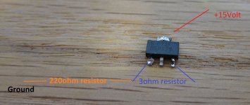
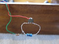
Still have the same problem... i tried again a brand new BSP129.
I made a simple test setup as in the picture. Still zero current so no voltage over the 220resistor.
Regards,
Hi,
I can assure you that this circuit when completed exactly as designed does work, and very well in this DAC.
I can only reiterate that your best chance is to *complete the entire circuit as shown by Peter* using the correct value components, and unless the components are down on spec the results must be OK.
I did mention earlier that resolving problems when there is a departure from the published design is not what I wish to spend my time on, but looking back at your original comments that placing a finger on the device seems to enable it to pass some current, suggests to me that you may have some stability problems here.
The added capacitance to ground resulting from the applied finger could be affecting this instability, although I have not experienced any such problems with any of these BSP129 devices myself - unlike the associated AD811 which is very sensitive to stray capacitance through poor layouts.
In this regard (and I don't wish to be overly critical here) that layout you show is rather a mess anyway, and when constructing the entire circuit you will need to keep all components very tightly together with minimal lead lengths etc, or you will have all kinds of problems for sure.
It is now after 1.00 AM here in the UK and I need some sleep now, but please don't expect others to resolve your problems for you unless you are fully-prepared to take the sensible advice given to you.
Regards,
Sorry to join this discussion so late, but i have a question:
Why use just one 1543 chip? (or two in balanced)
It seems that many designs use it paralled, and, indeed, i have made one with 4x tda's myself.
Is there an advantage to using only one? My measurments showed improvements in the 4x version, although the sound was not noticeably different to my ears.
Also i may be mistaken , but the balanced version is supposed to cancel bipolar zero error. (as well as providing double the swing and higher snr). There was a thread on this forums that claimed audible improvements in the balanced version.
Still have the same problem... i tried again a brand new BSP129.
I made a simple test setup as in the picture. Still zero current so no voltage over the 220resistor.
You need to build the regulator circuit exactly as posted, the complete version, then we can discussed the results.
I assume that copying the refined CS8412 circuit shown in this thread along with the updated regulator and removing the SN75179 be a useful upgrade to my AS NOS DAC kit, along with the TDA1543 upgrades I described above. Correct? I am intending keeping the circuit in an un-balanced mode for now.
And finally for Peter (and possibly Bobken)... have you tried the AD811-based shunt regulator in your phono circuit?
Yes, that's how I started my experiments with that DAC and all subsequent mods were bringing noticeable improvements.
The stock AS DAC is certainly quite good and years ago I would be hard to convince that it can be improved, knowing Bobken's attention to detail and exquisite taste, I gave it a try and there was no going back
")
It does not seem like like there is complementary device to BSP129 that can be used in negative reg circuit. Beside that, the shunt regulator I'm using in phono stage is quite similar, I chose there OPA627 as it's the same op amp used in gain stage.
Very useful reply. I get that there is a high level of synergy at play here and that changing topology and/or component choices will not produce the demonstrated and desired performance.
And I get that my 'I2S-connected, sound-card mounted, TDA1543 DAC-only' version will be a journey into un-charted territory. Still, I suspect it will be a worthwhile journey & I will start with as close of a clone of the unit as presented here, shorn only of the SPDIF front-end.
On updating my Peter Daniel DAC kit to this level while keeping it un-balanced, I still have a few questions...
1. Did you retain the 74ACT86 used for providing balanced data signal inputs into the DACs? That would seem to not be needed for an un-balanced implementation.
2. What coupling caps do you recommend?
I had intended to do both my 'sound-card DAC-only' version and the upgrade of my PD kit to a standard as close as possible to topology & components as laid out here. Looking it over, the Black Gate 2200uf/35v FK's and 1000uf/50v N's are going to be the hardest to obtain... Black Gates in general are getting to be very rare and those are going to be very rare. Luckily, I have the rest of the BG's needed in my dwindling stock.
It certainly shouldn't prevent you from trying the DAC directly with I2S sources. In fact I will be trying it soon with m2tech USB-I2S adapter board.
A good example of updating stock DAC kit to this level while keeping it un-balanced was presented here: http://www.diyaudio.com/forums/audio-sector/187748-pushing-limits-tda1543-nos-dac-2.html#post2551745
The guy still calls me and raves how good it all sounds
To keep it a reasonable cost I used MIT RTX caps and they seem to work fine. With single ended version the 74ACT86 is not needed.
Hello Peter and Bob,
i´m still loving the sound of my 1543-DAC and am always interested in
even making it better.
When upgrading with your regulators, as BG-N 10uF/50V are hard to find,
whats an alternative for this cap in the regulators?
Bob, you referred to the importance of the pll at the inputchip. What are
the actual parts to use here?
greetings Ulf
Hi,
I can assure you that this circuit when completed exactly as designed does work, and very well in this DAC.
I can only reiterate that your best chance is to *complete the entire circuit as shown by Peter* using the correct value components, and unless the components are down on spec the results must be OK.
I did mention earlier that resolving problems when there is a departure from the published design is not what I wish to spend my time on, but looking back at your original comments that placing a finger on the device seems to enable it to pass some current, suggests to me that you may have some stability problems here.
The added capacitance to ground resulting from the applied finger could be affecting this instability, although I have not experienced any such problems with any of these BSP129 devices myself - unlike the associated AD811 which is very sensitive to stray capacitance through poor layouts.
In this regard (and I don't wish to be overly critical here) that layout you show is rather a mess anyway, and when constructing the entire circuit you will need to keep all components very tightly together with minimal lead lengths etc, or you will have all kinds of problems for sure.
It is now after 1.00 AM here in the UK and I need some sleep now, but please don't expect others to resolve your problems for you unless you are fully-prepared to take the sensible advice given to you.
Regards,
You need to build the regulator circuit exactly as posted, the complete version, then we can discussed the results.
Hi,
Thanks for your inputs. I build the entire DAC and regulators as posted. When i turned it on the first time there where no voltage showing up on all 3regulators, that's why i build a dummy current source with the BSP129.
After further investigation today i notice that my BSP129's don't perform as the INFINEON or Siemens datasheets says. Both are different from each other. For both of them they can work with a 0 Vgs and still show current (Ida) between 80-150ma depending on the brand. My ones which i don't know the brand of unfortunately does not perform this way and needs a positive Vgs.
Any suggestions on where to get the infineon BSP129's?
Best regards,
You may check this post for possible substitutes, looks like Elna Starget is a good candidate: http://www.diyaudio.com/forums/digi...ansport-shigaclone-story-242.html#post2571790When upgrading with your regulators, as BG-N 10uF/50V are hard to find,
whats an alternative for this cap in the regulators?
Hi,
Thanks for your inputs. I build the entire DAC and regulators as posted. When i turned it on the first time there where no voltage showing up on all 3regulators, that's why i build a dummy current source with the BSP129.
After further investigation today i notice that my BSP129's don't perform as the INFINEON or Siemens datasheets says. Both are different from each other. For both of them they can work with a 0 Vgs and still show current (Ida) between 80-150ma depending on the brand. My ones which i don't know the brand of unfortunately does not perform this way and needs a positive Vgs.
Any suggestions on where to get the infineon BSP129's?
Best regards,
Hi,
I am sorry to hear this, especially as you said that you have 50pcs of them. In view of what you now say they must be fakes, which on reflection is perhaps not too surprising, because a 'genuine' BSP129 does not behave like that.
Had you mentioned earlier (when I first commented on the other reg components) that you had already tried 3 complete reg versions with identical problems, it would have saved some time and head-scratching perhaps, and I would have asked about their source as I did suggest the possibility of devices being out-of-spec.
For some obscure reason, since I have been using these depletion mosfets I have noticed worldwide shortages from time-to-time, a matter I mentioned to Peter when I first suggested that he might like to try this circuit in his DAC. At that time he also found they were not readily available, and the lead times at the UK distributers I checked for him were all for several months delays.
Around the time when I first used BSP129s I was involved in a commercial design with a tight deadline, and I had to abandon my intentions to use the devices as none were available and lead times were unacceptable then.
I obtained a batch of the only practical alternatives I was aware of, Supertex DN2540, but on checking the entire batch their parameters varied so much that the current-setting resistor would need to vary by 200% from the two extremes! This would result in the unacceptable complication and additional costs of measuring each individual device and selecting resistors on test, so they are not my preferred choice for this requirement.
IIRC, several of their parameters were substantially different as well from BSPs, and as an example I recall that the current-setting resistors needed to be considerably higher values for similar currents than the values I use in the BSP-based regs.
During the time when I have been using BSP129s, I have never seen any genuine devices offered for sale other than the Infineons, and I have done a lot of searching around. Accordingly, I would be wary of anything of unknown pedigree as it seems that whenever any devices are scarce or still popular after their discontinuation, there are unscrupulous vendors around who will take advantage of the fact.
Some years ago Peter, myself, and many other Forum members were 'taken-in'
with a group buy of discontinued dual J-Fets, but due to the integrity and efforts of the organiser who had himself been duped, most of us received most of our money back.
Hopefully, you will be able to recover your outlay, but as a favour to other members please tell us where they were obtained so they can avoid falling into the same trap.
Regards,
Guys, sorry for all the confusion, but it also looks like I made an error drawing the schematic: http://www.diyaudio.com/forums/digital-source/192342-pushing-limits-regulator.html
Hello Peter and Bob,
i´m still loving the sound of my 1543-DAC and am always interested in
even making it better.
When upgrading with your regulators, as BG-N 10uF/50V are hard to find,
whats an alternative for this cap in the regulators?
Bob, you referred to the importance of the pll at the inputchip. What are
the actual parts to use here?
greetings Ulf
Hi Ulf,
The PLL filter is a region I was intending to go into, anyway, so now is a good time to make some comments.
When I began trials with alternative components here, I was aware of the reasons for Peter's choice, IIRC mainly based on the popular "wildmonkeysect"
filter which had been adopted by many previous experimenters.
I had also researched all the comments I could find associated with this particular combination of components, and began to realise that it seemed everyone had more-or-less just followed this concept having found that it sounded better than the stock data-sheet suggestions. This was never likely to satisfy my curiosity, so I ignored what I had already become aware of, and started my own experiments based on the original parts chosen.
I have always been a fan of Black Gate caps (probably the first - or nearly so - to espouse their benefits and you only need to read some of my earlier postings on this Forum to see that!), and like Peter I decided initially to try BGs as he had done for the main PLL cap C11 on his original schematic.
In spite of being enthusiastic about their use in audio circuits which stems from discovering that nothing else gave me similar sonic satisfaction, BGs are not perfect electrolytics but there are none better in my view so this seemed a safe choice initially. I soon discovered that in opposition to the frequent suggestions and seemingly accepted-wisdom of my predecessors, increasing this cap's value excessively was a big mistake. I had seen comments about caps up to 1uF being touted, together with either very low-value series resistors (R6 on the orig. schematic) or even no resistor at all, until the circuit failed to lock onto the incoming digital-stream!
However, my ears soon told me that this was not the way to go as increasing the cap's value gave a fat slow sound as if everything was over-damped, and the entire life was missing from the sound. To cut a long story short (unusual for me!) after many months of intense trials together with hundreds of different resistor choices, I reached the conclusion that anything much above 0.2uF was just not good for the desired results, and this value was a problem with BGs. A particular problem here is that this region is sensitive to picking-up unwanted interference (although not quite as serious a problem as some had made-out) and virtually all other HQ caps had awkward lead-arrangements and/or were physically large and unsuited to this application.
I tried many other caps but nothing came close to the superbly clean BG 'sound', and as most of my 100+ stock of NX HiQ 0.1uFs measured at around 0.125uF I tried a couple of 0.47 NX HiQs in series to begin-with which was quite good. I also tried many other combinations of 3 in series & some in parallel etc BGs, but finally settled-on a pair of 0.1 in parallel which actually measure closer to 0.25uF jointly, a bit higher than I would really like. A single 0.1 is certainly superior sonically in most respects to going higher than around 0.2uF, but although many times since the original basic choice was made I have changed this cap's value again out of curiosity, I always come back to the 0.25-ish combination after a while.
This is again an example of needing to make the best out of what components are available and sounds good in the particular application, and unenlightened nay-sayers will doubtless criticise these situations severely, and say that this is just making matters harder than is necessary. Before anyone is tempted to do this, they should LISTEN to the results with what I have found to be the best (so far), and if they still believe that they have a better alternative I would be delighted to know what that is.
The other smaller cap (C10) is a real dilemma for me, mainly as I don't know of any cap made which is in the correct region of values and which 'sounds' as good as I prefer, and which is not far too large in size to be suitable here.
Additionally, according to the finest references I can find on PLL filters (mostly in Dean's Book) the earlier-suggested 3300pF C10 is far too low in value technically to do much good, anyway. It needs to be around (just under, actually) 10 times smaller than C11, ideally, if these sources are correct and in normal applications this cap is not specifically intended to change the filter's slope as much as overcome issues due to the resistor R6.
Also, this concept of making the filter 3-poles came originally from the later Crystal data-sheets which clearly state that the component-values etc do not apply to the earlier chips like the 8412 and I am less sure that the same concept is very effective with this earlier design.
******I don't know what just happened here, but as this is unfinished I didn't intend this to be shown yet, and I don't know how to withdraw it without losing the info. I will continue on another posting!!.
Last edited:
Hi Ulf,
Part 2.
Whatever, I have still been unable to find any suitable caps to try in this region which don't immediately spoil the entire sonic results to my ears although a tiny plastic-film Wima was the best, or rather the least damaging to the sound, out of all those I tried of a substantial value. Going smaller in values I like the high-rise polystyrene types which have a small footprint and 5mm lead-spacings, but as yet I don't find much (if any) sonic benefit when adding these, so for now I am still avoiding this cap altogether.
Moving on to R6, the short answer here is that I would not use any other type than a naked Vishay (TX2352 or the slightly better TX2575) after 'listening' to dozens of other choices here. The change in the sound is quite marked and for example using the same-values of Vishay (non-nude) like S102 is very poor in comparison, even though they are the same bulk-foil concept albeit with a molded surround.
As to values, actually I am still experimenting here and this value gets changed quite frequently as it is a handy means to tailor the resultant sounds, and this again can be fairly drastic. Going too low in value provides a lacklustre effect in comparison as if the extreme upper frequencies are being truncated. This would be similar to a low-pass analogue filter where the -3dB point is lowered a little, although I confess that I don't know why it should particularly affect the HF more than any other frequency in the digital stream, and it is perhaps unintuitive. It becomes a tame sound somehow for want of a better sonic discription, but going higher in value for R6 one starts to hear more-obvious distortion effects typical of jitter. This can appear to be more lively but there is far too much distortion in this circuit already, and for me I would rather not add to this if it is avoidable.
On this subject, of course the HF is troublesome anyway due to the way we use this TDA chip, and checking with a 'scope shows that over a few kHz, sine waves are getting badly distorted to the extent that had I seen this first, I would not have believed that the results were even worthwhile listening-to. This is another regrettable problem with these kinds of DAC, of course, but they can and do sound quite extraordinary in spite of all of their technical shortcomings.
A conclusion I have reached more-recently is that there is an 'optimum' breakpoint for this PLL filter to sound at its best, and from my experiments the R-C time-constant I have reached by hundreds of hours of empirical trials happens to be very close to the Crystal Data-sheet recommendation.
Presently, with my C11 value I am working in the region around 180R for R6, and Peter's choices are perhaps not-coincidentally very close to this same time-constant, also apparently judged by ear.
I can readily hear changes of less than 10 Ohms here for R6, which surprised me a lot being such a small percentage variation, but again this is the nature of this particular rather 'touchy' circuit where we are trying to get the very best perceived sonic results out of a (sometimes!) bad bargain.
There is possibly some merit in exploring a separate clock/PLL filter sometime, but so far I have enjoyed the challenge of avoiding further complications to the circuit, and some others including Peter don't always agree that these are an overall improvement. Besides, I might lose the opportunity of using this region to 'tune' the results I guess, and that would spoil the challenge and probably some of the fun, and because other caps are not perfect in this design, the tuning facility is quite useful.
Regards,
- Home
- More Vendors...
- Audio Sector
- Pushing the limits of TDA1543 NOS DAC