Got my spare chip today and have wired it up properly and sat here listening to it.
Conclusions: For a non "power" amp it has got a lot of drive, but then again I have two speakers working and not just one so I always expected for the volume to be set lower.
The bass has come back to me and it's less bright now, but again that's not surprising as I had 12A going to just the one channel until today (two 6A secondaries), and I always wondered if the greater ampage was making it too bright.
The sound is nice and warm too.
Next steps: Listen to this like it is for a couple of weeks and then build myself a pre-amp as per Nuuk's site and see what difference that makes.
Okay, I swapped out my bridge for the spare one and re-filed the tips of my secondary wires. I think I've got that licked. Although the DC voltage coming out seems high....
What really bugs me is that my LED still won't work!!! Is it possible to cook the led while soldering it's points? Should I try ordering up a fresh one?
What really bugs me is that my LED still won't work!!! Is it possible to cook the led while soldering it's points? Should I try ordering up a fresh one?
Grounding?
Quick question. Is the Input Signal ground a completely seperate ground from all the other grounds (including the chip ground) - i.e no physical connection between the two?
If so, why?
And if it isn't seperate then why not just connect the input ground directly to the star ground?
Quick question. Is the Input Signal ground a completely seperate ground from all the other grounds (including the chip ground) - i.e no physical connection between the two?
If so, why?
And if it isn't seperate then why not just connect the input ground directly to the star ground?
All grounds are connected together, they must be connected together. However, in my setups, the star ground is for power ground only and I prefer to keep signal ground separately, that's why the wires from RCAs (or potentiometer) connect directly to amp board and not to power star ground.
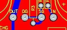
Peter Daniel said:There is a spot for a LED on rectifier board and I like the small Panasonic LEDs available from DigiKey (part# P612). With those LEDs, 62K series resistor is required (R3 on rectifiers board, the long pin from the LED connect to square pad).
I can't find a thread that is dealing with my issue, but I am hoping it wouldn't be a problem for me to post the question here, since I see a resolution to my issue in the quote above.
I am attempting to build my first chipamp based on LM3875 and I hit a small roadblock. Since I am using very small heatsinks and the amp enclosure will have bad air circulation, I was planning to add a 12V fan to it. My knowledge of electronics is very limited, but I was able to get my dual mono board to work, while using a 9V battery to power the fan and cool the heatsinks. I have Avel Y236651 250VA 18V+18V transformer, but my multimeter reads 27.1V of DC power coming out of the rectifier board (4 MUR860s). I added a 63.5K resistor to the circuit and the voltage dropped only to 25.5V. Based on the above quote, a 62K resistor would drop 21.7V output down to 2.2V.
So my question is: how would I calculate, which resistor I need to get an output of 12V from 27.1V DC?
Thank you in advance for help!
Peter Daniel said:..snip..
I usually use trimpot to adjust diode brightness or fan speed and then replace it with fixed resistor.
Now that is a VERY good idea!!!!

I've been listening all day now and am so thoroughly impressed.
Peter you once remarked that you were considering a pre-amp, I don't know if you meant phono or linestage or what?
Is this something that we can still expect to see? I think there would be lots of interest? Phono or otherwise I would love to have another Peter Daniel in my arsenal.
Peter you once remarked that you were considering a pre-amp, I don't know if you meant phono or linestage or what?
Is this something that we can still expect to see? I think there would be lots of interest? Phono or otherwise I would love to have another Peter Daniel in my arsenal.
I'm glad to hear that you're happy with the amp.
As to a preamp, I never really went into active designs as I don't think they can do any good and most of the time they just degrade the sound. The amp's gain is pretty high so installing potentiometer at the input is most cost efficient solution.
I have phono preamp project coming and I will soon be finalizing it.
In a meantime, you can always try NOS DAC
- Home
- More Vendors...
- Audio Sector
- Commercial Gainclone kit- building instructions