It's 28V without caps on the rectifier board, but with the amplifier boards fully populated and hooked up (no input signal or speaker load). My transformer dual secondaries are 21V each. If I recall correctly, the rectifier board without the amp boards was putting out 19V into V+/PG+.Is this 28V with caps or without? You can do any of that on rectifier board, but I can't confirm it will work with your subwoofer trigger circuit.
I actually finished the basic GC build last night and have already confirmed it is working. (I'll reserve pronouncements about its sound quality until I have a chance to crank up the volume without waking up the household in the middle of the night.)
This evening, I'll try adding the subwoofer trigger and see if it works. If it doesn't, I can always tweak the resistor value, or switch to a voltage divider with two resistors, or remove it entirely and get off my butt to turn the subwoofer on/off manually.
Can anyone confirm what the correct size is for the nut on those Noble potentiometers? I ordered a few and have my amp fully assembled outside of 2 nuts for volume pots 
They appear to be M8 but they are a finer pitch/thread than 1.0 and unfortunately, thats the finest thread they carry at my hardware store.
Thanks for any assistance!
They appear to be M8 but they are a finer pitch/thread than 1.0 and unfortunately, thats the finest thread they carry at my hardware store.
Thanks for any assistance!
I'm not sure which specific Noble pots you're referring to, but some of theirs use M7 x 0.75mm thread and others use M9 x 0.75mm.Can anyone confirm what the correct size is for the nut on those Noble potentiometers? I ordered a few and have my amp fully assembled outside of 2 nuts for volume pots
They appear to be M8 but they are a finer pitch/thread than 1.0 and unfortunately, thats the finest thread they carry at my hardware store.
12 Volt Trigger Output
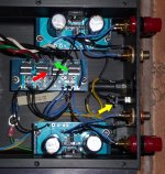
As discussed in earlier posts, I was looking to create a 12 volt trigger output from my GainClone to switch a subwoofer on and off. It's now up and running fine. Here's what I did:
The attached photo shows the inside of my amp. I made a voltage divider based on the portion of the rectifier board designed for an LED. The first resistor (R1 in voltage divider terminology) is mounted to the resistor space labeled R3 on the rectifier board (red arrow). The two wires to handle the trigger output are connected to the LED space (green arrow), with the positive lead in the hole with the square marking. Those wires connect to a 1/8 inch jack in the rear panel (yellow arrow). The second resistor in the voltage divider (R2) needs to connect across those two wires. Rather than mount R2 at the cramped rectifier board, I simply moved it to the other end of the two wires, at the jack.
On my board, I had 28 volts coming off the rectifier (powered by 21 volt transformer). I used the calculator at Voltage Divider Calculator, entering 28 for the "battery voltage", 0.020 (20mA) for the current, and 12 for Voltage Out. The calculator gave me back resistor values of 800 ohms for R1, and 600 ohms for R2. I actually used 820 and 620 ohm 1/2-watt resistors, and the circuit produces a measured voltage of 11.8, triggering my subwoofer very nicely.
Now for the tricky part. When I hooked up the amp in my system with the trigger connected to the subwoofer via a cable with 1/8-to-1/8 inch plugs, I got noticeable ground loop hum. The subwoofer and the GainClone are both connected to preamp ground through their interconnects. (The preamp has dual sets of outputs.) So I modified the trigger cable between the GainClone and subwoofer to disconnect its ground wire, and the trigger is now carrying only +12V. If I had known about the ground loop in advance, I could have wired up the voltage divider in the GC with only one wire, although in that configuration the R2 resistor (620 ohms) would have to go at the rectifier board, bridging the two LED holes. (The trigger output wire has to have the R2 resistor between it and ground.)
If anyone else wants to give it a go, just make sure to calculate the resistor values for your actual voltage on the rectifier board with the amplifier boards hooked up.
Attachments
Last edited:
Here's my first effort at a gainclone amp. I managed to destroy the Noble pot by getting it too hot while soldering the wires too close to the body. Other than that the build went without a hitch, though way more time was spent machining than soldering.
For now, in place of the pot, I'm running with a few resistors on a bread-board borrowed from my son. I've got about a dozen hours on the amp now, i'm trying some higher volume levels tonight, and to my untrained ears, the sound is just wonderful.
The chassis is machined from a block of aluminium - plenty of mass, but not a lot of surface area for shedding heat. At the higher volumes, it does get a little warm. I'm wondering: What is a reasonable maximum temperatureand is there a significant risk of speaker damage with overheating?
Peter - Many thanks for all that you are doing here!
Cheers,
Dave
Attachments
Oscillation in LM 3875 Audiosector Board
Hi,
I need help
I assembled a stereo amplifier with the boards purchased from you and I need help.
The configuration is as below.
Power-18v+18v AC -Avel 160 VA Toroidal Transformer
Speakers-8Ohms
Input to the amplifier- Ipod
The amplifier works well except for the following.
1) Music is playing from the Ipod.
2) The ipod is switched off
3) The Ipod is switched on
4)THERE IS SINUSOIDAL SOUND COMING FROM THE SPEAKERS(THERE IS AN OSCILLATORY SURGE).THE CHIP BECOMES HOT.
5) AFTER 10 TO 15 SECONDS THE MUSIC COMES ON AGAIN
Is there something wrong that I am doing.I do not have a volume control and am depending on the Ipod volume control to decisde the out put.
I would appreciate if you any body in this forum can suggest something
Thanks in advance
Hi Peter,
I got your classic kit, thank you. And now it time for my second Audiosector amp.
I have one question, may be of interest for someone else: I want to build an amp with pot and external psu, similar to your Patek. On your site I see that the Patek umbilical coming from the PSU has 4 wires V+, PG+, V-,PG- I suppose.
Since I already have some Neutrik 3 pin XLR connector, can I use them?
To do it, I would connect PC+ and PG- in the PSU box, than a 3 wire umbilical (V+,V- and G).
In the amp chassis I would make the star ground as you suggest in this thread.
And finally, what about the PSU chassis ground? Should I connect the Neutrik common ground to the chassis? I know you showed somewhere the diagram, but I could not find again.
Thank you
Renato
Hi,
I just realize my chipamp with the lm4780 kit configured in paralell have some high frequency oscillation problem, It amplifies rf frequency. I know that one maner to solve the problem is to install a 300pf cap at the inputs of the chip. As the lm4780 is like 2 lm3886, do i need to install 2 caps per chip ? one cap at pins 15-16 and another at pins 21-22.
Thanks
Hi,
I just realize my chipamp with the lm4780 kit configured in paralell have some high frequency oscillation problem, It amplifies rf frequency. I know that one maner to solve the problem is to install a 300pf cap at the inputs of the chip. As the lm4780 is like 2 lm3886, do i need to install 2 caps per chip ? one cap at pins 15-16 and another at pins 21-22.
Thanks
Finally, I solve the problem. I install two 100pf caps at pins 15-16 and 21-22. I did the same trick with the lm3875, because the zobel network didn't cure the rf frenquency oscillation. With 300pf the reducing bandwith is audible.
I want to build an amp with pot and external psu, similar to your Patek. On your site I see that the Patek umbilical coming from the PSU has 4 wires V+, PG+, V-, PG- I suppose.
Since I already have some Neutrik 3 pin XLR connector, can I use them?
To do it, I would connect PC+ and PG- in the PSU box, than a 3 wire umbilical (V+,V- and G).
In the amp chassis I would make the star ground as you suggest in this thread.
And finally, what about the PSU chassis ground? Should I connect the Neutrik common ground to the chassis? I know you showed somewhere the diagram, but I could not find again.
Yes, using 3 pin Neutrik and connecting both grounds in PS will work too. PSU chassis ground should be connected to mains ground.
- Home
- More Vendors...
- Audio Sector
- Commercial Gainclone kit- building instructions