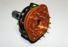
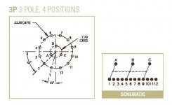
Attached is a schematic for such a switch.
For stereo application we use only 2 poles, lets say A and B, which connect to pins 1-4 and 5-8 respectively. Pole C is not being used.
We only need to switch signals, the grounds are common and usually not switched.
Pin 1 connects to left channel of your first source, pin 5 to the right channel of your first source (connected to RCA inputs).
Pin 2 to left channel of second source, pin 6 to right channel of the second source, and so on for other two sources.
Pole A is a left channel output, pole B is a right channel output from a switch, and they connect to the potentiometer.
Attachments
Source selector
Thank you Peter, you have been very kind and detalied in your answer as always.
Just last question (I hope): where should I connect all the RCA input grounds? All left channel grounds together to the left amplifier PCB input ground and all right channel grounds together to the right amplifier PCB?
Thank you again
Renato
Re: Source selector
That is correct. The amp board input ground is marked SG, this is also the point where ground from potentiometer connects.
northernsky said:where should I connect all the RCA input grounds? All left channel grounds together to the left amplifier PCB input ground and all right channel grounds together to the right amplifier PCB?
That is correct. The amp board input ground is marked SG, this is also the point where ground from potentiometer connects.
Hello Peter,
I have been listening to my first chip amp for few days now and have been really happy and imressed with the music it is making. But i do realise that there is much potential for improvement. So, i dont just want to sit back and be content with what it has to offer, rather to keep improving it perpetually as far as i can.
Having read through the posts in this forum, i understand the following ways can improve the sound quality of this amp.
- A better case with shortest signal path and good quality connectors. (given that mine is currently housed in a large sized case, wired with ordinary wires)
- An input buffer, preferably a tube one. (there are few which seem popular here, but which one do you reckon is worth the effort and more importantly which one does not ruin the basic sound signature of this amp)
- Premium components (though i feel that it already has premium components installed as its a premium kit. Still just want to know is there is any possibility)
However, i am not very sure as to which one is better than the other or if one is good at all. I would appreciate if you could guide me here as to which one of the above is more promising and important in terms of effort to gain ratio. Also, if there are other ways which i have not yet found, please do let me know.
My speakers are Wharfedale Diamonds 9.1 and source is Squeezbox -> NOS DAC.
Cheers.
Black Gate Capacitors!
mubeen, if I may contribute in something.I used the "premium parts" too, but I was like you.I was trying to get the most of these amps.so I decided to change the capacitors from Panasonic capacitors 1500uf (premium kit) to "Black Gate" capacitors 1000uf 50v.
The result was a huge improvement!,of course these caps cost a lot,but it was worthy all the way!.Some people do not hear a difference ,but I did an A/B test with Black Gate capacitors and they are the BIG improvement that you are looking for. Remember to let the capacitors "run" for at least a month or so.
Good Luck buddy!")
mubeen, if I may contribute in something.I used the "premium parts" too, but I was like you.I was trying to get the most of these amps.so I decided to change the capacitors from Panasonic capacitors 1500uf (premium kit) to "Black Gate" capacitors 1000uf 50v.
The result was a huge improvement!,of course these caps cost a lot,but it was worthy all the way!.Some people do not hear a difference ,but I did an A/B test with Black Gate capacitors and they are the BIG improvement that you are looking for. Remember to let the capacitors "run" for at least a month or so.
Good Luck buddy!
I expressed some thoughts on further upgrades to a premium kit here: http://www.diyaudio.com/forums/showthread.php?postid=1231532#post1231532
More reading on capacitor comparisons can be found in those links:
http://www.diyaudio.com/forums/showthread.php?postid=574431#post574431
http://www.diyaudio.com/forums/showthread.php?postid=581230#post581230
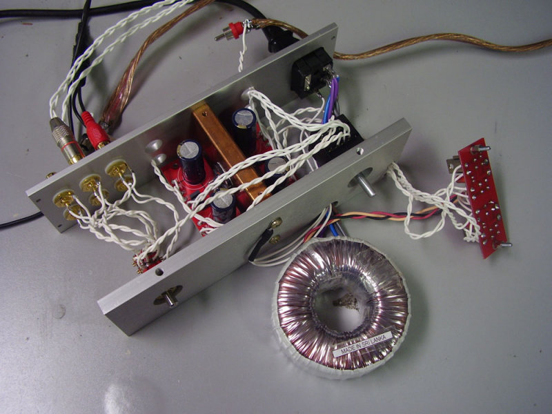
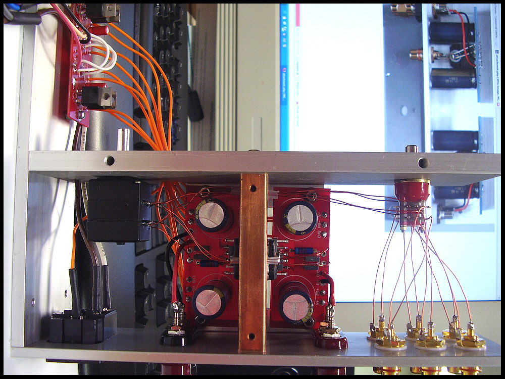
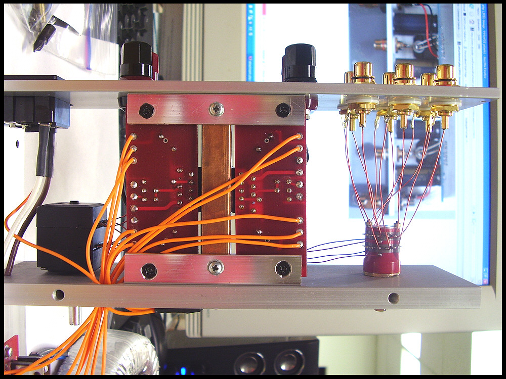
Better case is certainly important if you want to get the best out of the amp. My present amp was described in this thread: http://www.diyaudio.com/forums/showthread.php?s=&threadid=76609&highlight= and here I pushed the GC concept as far as I thought was possible
Personally, I don't like buffers in the amp, the buffer should be placed with a source. A simple fet buffer works fine with NOS DAC, one such example is buffer described in Figure 15C in Borberly article: http://www.borbelyaudio.com/adobe/ae699bor.pdf
At the amp's input, a swtching attenuator is usually preferred (25k or so).
More reading on capacitor comparisons can be found in those links:
http://www.diyaudio.com/forums/showthread.php?postid=574431#post574431
http://www.diyaudio.com/forums/showthread.php?postid=581230#post581230
Better case is certainly important if you want to get the best out of the amp. My present amp was described in this thread: http://www.diyaudio.com/forums/showthread.php?s=&threadid=76609&highlight= and here I pushed the GC concept as far as I thought was possible
Personally, I don't like buffers in the amp, the buffer should be placed with a source. A simple fet buffer works fine with NOS DAC, one such example is buffer described in Figure 15C in Borberly article: http://www.borbelyaudio.com/adobe/ae699bor.pdf
At the amp's input, a swtching attenuator is usually preferred (25k or so).
Attachments
By-pass capacitors on Pateks?
Peter,
As you know I have built several of the Patek style amplifiers (i.e. using BG caps) and I was wondering if there was any advantage in using by-pass caps on either the regulator (1000uF STD) or the amplifier (50uF Non polar) capacitors?
Whilst trying to sort out my multi-amping of my active speakers I started listening to a single pair of these amps powered by the Polish transformers - my Spendor BC1s have never sounded this good!
Alan
When all is done right, the bypass caps never seem to improve things, IMO. Sure, you may perceive certain gains, but that can be always compared to using equaliser, and while certain frequencies can accentuated, overall harmonic integrity is affected. A single cap of high quality is far better, and far less damaging to the sonic signature of a given circuit.
What I mean is, no bypass caps of any kind, whatsoever. Single cap only, but carefully chosen.
What I mean is, no bypass caps of any kind, whatsoever. Single cap only, but carefully chosen.
Peter Daniel said:I expressed some thoughts on further upgrades to a premium kit here: http://www.diyaudio.com/forums/showthread.php?postid=1231532#post1231532
More reading on capacitor comparisons can be found in those links:
http://www.diyaudio.com/forums/showthread.php?postid=574431#post574431
http://www.diyaudio.com/forums/showthread.php?postid=581230#post581230
Better case is certainly important if you want to get the best out of the amp. My present amp was described in this thread: http://www.diyaudio.com/forums/showthread.php?s=&threadid=76609&highlight= and here I pushed the GC concept as far as I thought was possible
Personally, I don't like buffers in the amp, the buffer should be placed with a source. A simple fet buffer works fine with NOS DAC, one such example is buffer described in Figure 15C in Borberly article: http://www.borbelyaudio.com/adobe/ae699bor.pdf
At the amp's input, a swtching attenuator is usually preferred (25k or so).
Thanks very much for the valuable info Peter. I checked and read through the links you have given here. And I completely agree that GC in its original form is probably the best GC. As there is certain naturalness and delicate harmonic balance in its sound which might easily be lost by sticking anything before or after it. If aint broke, dont fix it, so i wont
But i see that you suggested using BG 100uf N caps on amp boards. I would like to try this mod and see if i can get better clarity in vocals and higher mids. I understand that i would need to replace existing Panasonic FC caps on amp board with same number of BG 100uf N caps? Please correct me if i am wrong.
Saw your case work and i must say its a masterpiece. simply awesome! i would love to build something like that someday. For now, lets see if i can build a simple and neater case
Sorry for my ignorance but where exactly do we use the switched attennuators? Is it a substitute for volume pot?
Also, currently i am using a 100K pot for volume control as it was the only one available at the time i was building. I still need to order the Nobel one. Does this value affect the amp in anyway? I should be using something in range of 20-50K, isnt it?
Can i safely remove the input resistor without affecting the amp in anyway and would it help to improve sound?
Cheers!
Yes, the 220R input resistor in most cases can be removed, especially if you have potentiometer.
I actually meant stepped attenuator in place of potentiometer, which is probably more popular term, a recent discussion can be found in Blowtorch thread: http://www.diyaudio.com/forums/showthread.php?postid=1568061#post1568061
100k will work but it's a bit too high, the potentiometer should preferrably be in a 10k-25k range, 50k being maximum.
On amp board my first choice is indeed BG N 100/50. For mids and highs you don't need any additional caps here and those small BG N will give you the best sonic signature I experienced so far from a GC. However, for full range they are not enough to smooth PS ripple and some hum will be present; that's why additional BG STD 1000/50 are placed at rectifiers. The latter may also further improve bass response.
Have you try this Peter?
Peter,on your boards "LM3875".on the PS board.you use small caps 4.7/10uf 50v , and 1500uf caps on the "chip" board.
one time I was trying differents caps on the rectifier board and instead putting small caps on the rectifier board,I used Panasonic 1500uf 50v and Black Gate 1000uf 50v on the "chip" boards.and I do not kbow but I liked the sound better with the 1500uf caps on the bridge rectifier...I got better or more bass.can this be possible to leave the 1500uf caps on the rectifier board and the 1000uf BG on the "chip" boards?.

Thank you!
Peter,on your boards "LM3875".on the PS board.you use small caps 4.7/10uf 50v , and 1500uf caps on the "chip" board.
one time I was trying differents caps on the rectifier board and instead putting small caps on the rectifier board,I used Panasonic 1500uf 50v and Black Gate 1000uf 50v on the "chip" boards.and I do not kbow but I liked the sound better with the 1500uf caps on the bridge rectifier...I got better or more bass.can this be possible to leave the 1500uf caps on the rectifier board and the 1000uf BG on the "chip" boards?.
Thank you!
What is the best way to hook up an LED to one of the original rectifier boards?
Have a read here .
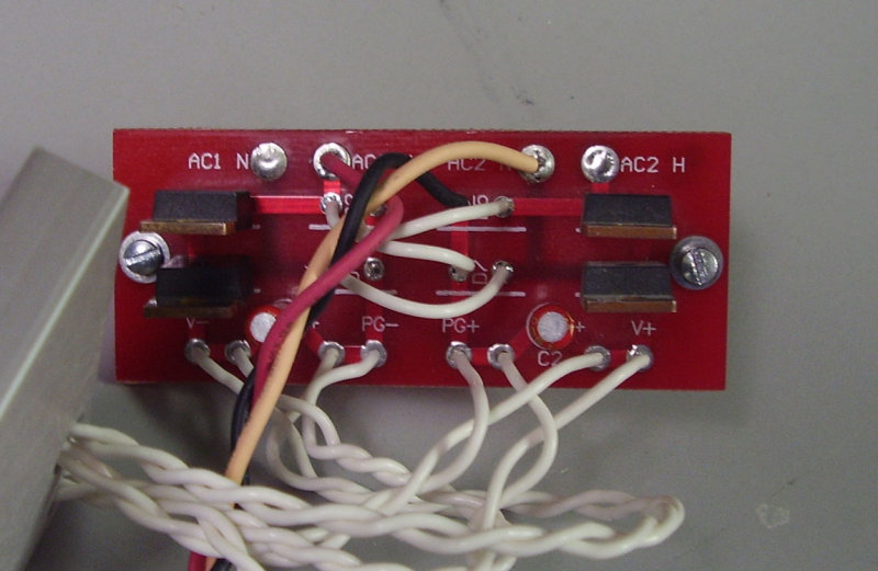
does my wiring look OK, or should I get rid of all the braides and twists?
With those lengths it's really down to aesthetics so you are the best judge of what you are happy with.
Thanks Nuuk. I like the magnet wire idea, so I bought a roll. Then I got a stupid idea to rewire the amp, since I didn't like my first attempt.
So... now that it looks nicer, now my right channel does not work! I triple checked every connection with a meter, and also checked for cold solder joints. every pad on the right channel seems to match with the left. Did I kill the chip?
So... now that it looks nicer, now my right channel does not work! I triple checked every connection with a meter, and also checked for cold solder joints. every pad on the right channel seems to match with the left. Did I kill the chip?

mattjk said:Did I kill the chip?
What offset do you measure on each channel? Does the offset change when adjusting volume?
Re: Have you try this Peter?
Sure, if it works better for you
lanchile07 said:Peter,on your boards "LM3875".on the PS board.you use small caps 4.7/10uf 50v , and 1500uf caps on the "chip" board.
one time I was trying differents caps on the rectifier board and instead putting small caps on the rectifier board,I used Panasonic 1500uf 50v and Black Gate 1000uf 50v on the "chip" boards.and I do not kbow but I liked the sound better with the 1500uf caps on the bridge rectifier...I got better or more bass.can this be possible to leave the 1500uf caps on the rectifier board and the 1000uf BG on the "chip" boards?.
Sure, if it works better for you
- Home
- More Vendors...
- Audio Sector
- Commercial Gainclone kit- building instructions