Adjusting the phase offset gives you a real and meaningful improvement in vibration. Fiddling with motor drive voltage largely just reduces torque and is a crutch for incorrect phase offset.
so how does on go about measuring a motor? what do you need to do to adjust the phase offset? Do the individual windings need to be measured and what equipment is necessary to do this? I have an AC motor which vibrates too much to use perhaps this is all that is wrong? Thanks for any assistance or direction. Best regards Moray James.
it's a french motor a Cruzen I think. I have the manufacturers suggested capacitor value. What would I expect to see for winding resistance values? Is going to be something I can measure with a multi meter? I do have access to an inductance meter as well. Should I be starting with a smaller cap and add the trimmer cap on? What is the process? Do I simply adjust the value till running operation seems smoothest or is there something specific to measure for? Thanks. Best regards Moray James.
If you have the manufacturers value then there's little point bothering to calculate it based on measuring the motor, so skip that step.
I would start with 10% less than manufacturer recommended capacitance and work through increasing it to 10%+, via a trimmer or maybe substituting smaller cap vales to home in on a rough value.
If you hold the motor in one hand while it is turning you will feel the vibration increase and decrease as you adjust capacitance. I found the best value for mine was just under 0.2uf, the manufacturer recommended valuer is 0.22uf, the difference was significant both in vibration felt through the hand and also from a full speed demodulation produced from a 3k test tone when it was re-fitted to my deck. There's a great thread on Pinkfishmedia in the diy section called 'turntable sped analysis', there's a lot of good info in that thread.
http://www.pinkfishmedia.net/forum/showthread.php?t=70027
Last edited:
The second is a resonance between the moment of inertia of the rotor and the electromagnetic torque "spring" caused by the drive current being greater than the stall value at the output torque, which causes the angle between rotor and stator field to reduce. Since this is related to the difference between drive voltage and "generator voltage", the higher the drive voltage the worse this effect. It isn't as easily solved as the above effects and my first attempts were either abject failures or impossibly complex to implement. I'm still searching for a good simple solution to this one.
This is very interesting and is an area that I have investigated (and had some considerable success - sq225917 has taken part in my investigations).
This is very interesting and is an area that I have investigated (and had some considerable success - sq225917 has taken part in my investigations).
Unfortunately, the above post has been misunderstood (my fault - too succinct); what I meant was that sq225917 and I have shared ideas and experience - he has also done a great deal of investigation with regard to power supplies (which I have been lucky enough to participate in - though have had no input).
Many thanks.
As an aside, as a result of your recent investigations in to power supplies (not to mention your generosity in actually providing the parts), I built this yesterday:
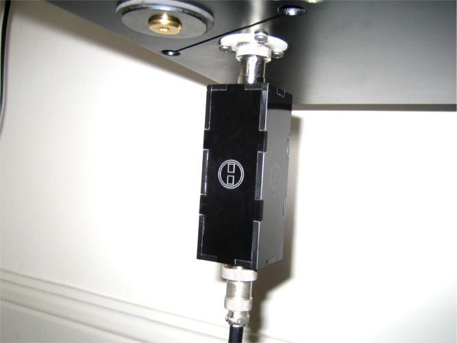
That's the underside of my turntable by the way") .
.
I'm surprised by how much difference this mod has made; the leading edge of notes seems noticeably more defined - I wonder what the measurements would tell us.
As an aside, as a result of your recent investigations in to power supplies (not to mention your generosity in actually providing the parts), I built this yesterday:
That's the underside of my turntable by the way
.I'm surprised by how much difference this mod has made; the leading edge of notes seems noticeably more defined - I wonder what the measurements would tell us.
Blimey now there's an indulgence, I like it.
To be honest having seen the results of the recent speed test FM demodulations I don't think there's much more to learn from more measuring. We are basically at the limit for the test pressing used. Maybe it's time to waste £100 on that genuine DIN test record.
I'd be interested to see some wavelet analysis, I think it was Dom who showed that on PFM, as that easily identified the difference between your deck and mine vis-a-vis your lack of 33 1/3 signature noise due to you not having a point contact on your mag-lev main bearing.
It could be interesting to see some spectral from the motor feed and indeed feedback, I suspect there maybe some reduction of higher frequency harmonics. If I could arsed I'd buy that PS Audio regenerator and drive to Gwent to collect it, that could prove interesting- or an expensive waste of money.... ;-)
It runs both ways, back emf from the motor pollutes the traffo in the Geddon and HF crap already on the mains does the same to the motor. Nothing's perfect.
How did you attach them in the end, one one each positive phase? I guess you could do with another for the return. I did mine, one across both phases- before the split and one on the return. 3 might be better... I'll wind some more.
How did you attach them in the end, one one each positive phase? I guess you could do with another for the return. I did mine, one across both phases- before the split and one on the return. 3 might be better... I'll wind some more.
Dear all
For very old turntables, like Pioneer PL12D, CEC BD2000, the AC motor vibration is not acceptable. The AC motor runs at about 1500rpm from the mains. A simple modification can be done using a 3 speed DC motor from Ebay (Matsushita clone from China) It has a IC speed controller AN6651 for speed control. The motor is less than USD $5 and works very well. Vibration is totally eliminated, and speed is spot on (using speed check disc).
For TT with AC motors (and you want to keep the old motor), the only way to reduce the inherent vibration is to control BOTH the per phase voltage and the phase angle lags between the phases. I have found that due to manufacturing/ tolerances/ design, a 90 degrees phase difference cannot guarantee completely elimination of vibration. Feeding the motor with a pure since wave source, with the phase delay capacitor, may or will not reduce the vibration enough (might as well keep using the mains).
Below is an account of how I completely removed the vibration on the Dual AC motor. I have used the same power supply on other TT of different manufacturers (per phase voltage controllable 80-110V ac and phase angle control) I could get the AC motor run like a very quiet DC motor. I have learned many things from this thread so this may be a compilation and summary. Thanks.
Synchronous Motor Driver for Dual CS522 or CS505 using SM100-1 motor
Last edited:
- Status
- This old topic is closed. If you want to reopen this topic, contact a moderator using the "Report Post" button.
- Home
- Source & Line
- Analogue Source
- Methods for Reducing Turntable Motor Vibration