I've looked around to see what is available that might be used for the transistors.
It's interesting that neither the BC560/BC860 or BC550/BC580 are labelled as low noise types.
The types that come as low noise on Mouser have no PNP complementary.
Apparently there's another complementary option to the SLN BCs, which are:
MMBT4124 ON Semiconductor / Fairchild | Mouser
MMBT4126 ON Semiconductor / Fairchild | Mouser
They come in TO92 and SMT versions, so you can choose. Even so, pairing between NPN and PNP versions would probably be quite difficult or not even possible.
But I wonder if a THAT quad, with two NPNs and two PNPs, being low noise, would not work.
340P14-U THAT | Mouser
Last edited:
Hi.
What would be the particular benefit of making a RIAA stage particularly compact or particularly small, as with the addressed SMD components?
Even if you could put the whole (pre-)amp in your pocket, you always need the turntable, and that will make the whole thing cumbersome/stationary again.
What would be the particular benefit of making a RIAA stage particularly compact or particularly small, as with the addressed SMD components?
Even if you could put the whole (pre-)amp in your pocket, you always need the turntable, and that will make the whole thing cumbersome/stationary again.
I am not a fan of SMD projects or parts, so I'm probably the wrong person to answer your question.
Benefits:
1) Very small distance between parts. That sometimes is difficult to achieve with through hole parts.
2) Availability. Nowadays it's easier to get SMD parts than through-hole, particularly semiconductors. Sometimes they are even cheaper.
3) Small size. You can put the preamp on the turntable, eliminating interconnect cables between cartridge and preamp. Shielding it would also be easier.
Cons:
1) Anti-DIY. Most SMD parts are extremely difficult to handle.
2) Fragility. SMD parts are more easy to ruin, particularly by heat, when soldering.
3) Loss. You can lose the part quite easily, which is a problem with expensive active devices.
4) Soldering. You need specific tools, not cheap.
5) Thin tracks. SMD parts belong in SMD pcb designs. Tracks are very thin and very damage-prone.
Well, the list may be longer on both for and cons.
??? don't know, is this what you want:
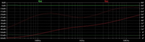
see attached pic of frequency response.
red: input signal after reverse RIAA
green: output signal.
amplification at 1kHz = 35db
Distortion:
In LTSpice try to change the signal, which you want to examine
e.g. from: ".four {f} V(o) " (output)
to: ".four {f} V(e)" (amp input = reverse riaa output)
see attached pic of frequency response.
red: input signal after reverse RIAA
green: output signal.
amplification at 1kHz = 35db
Distortion:
In LTSpice try to change the signal, which you want to examine
e.g. from: ".four {f} V(o) " (output)
to: ".four {f} V(e)" (amp input = reverse riaa output)
Attachments
In the real amp (pic, post #157) with pots "PP" / "PN" set to the 100 Ohm region I noticed the output transistors getting a bit hot.With the servo you can omit the resistors PP and PN (= 0 ohms).
With the above mentioned 0 Ohms the simulation shows 130mW dissipation. To high for a TO92-Device without cooling, I think.
I changed the pots to around 5kOhm. The simulation then shows around 75mW dissipation.
In the real amp then is a light warming.
With the pots (PP, PN) it is possible to set the output dc offset to about 1mV or lower.
Less to do for a DC-Servo.
Maybe depends on what you define as input.What I mean is if you look at the input sinusoidal level and compare to the output sinusoidal level, there was no amplification.
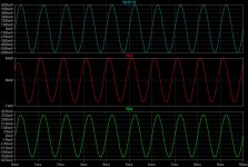
The following pic shows three sinus-signals (1000Hz):
On top the signal coming directly from the AC-source (600mV)
In the middle the signal which the RIAA-preamp "sees" at it's input (6mV @ 1000 Hz). This is also the output of the reverse RIAA network which attenuates the signal from the AC-source in a frequency dependent manner.
On the bottom the output-signal of the preamp. (360mV)
Attachments
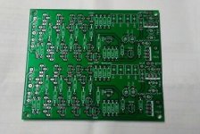
link to buy...the printed circuits are back available ... who is interested let me know with p.m. thank you
diy pcb circuito stampato preamplificatore phono MM ELEKTOR SLN | eBay
Scafas,
Your pcb boards look very well done, and the price is very nice.
But there's an important change that I think should be considered, maybe for another series: the power supply.
Those 7X15 regulators certainly do not do justice to the quality of the preamplifier.
LM317/LM337 or LT1085 should be the minimum quality to be considered, with proper filtration and all.
The importance of the power supply has not been sufficiently discussed on this thread.
If I were to use your boards, I would try several external regulators and particularly a Jung superregulator, which might make this preamp shine.
The DC offset adjusting trimpots mentioned above could be avoided if those THAT complementary blocks are used, as you wouldn't need as many devices as the Elektor design uses to lower noise.
Maybe depends on what you define as input.
The following pic shows three sinus-signals (1000Hz):
On top the signal coming directly from the AC-source (600mV)
In the middle the signal which the RIAA-preamp "sees" at it's input (6mV @ 1000 Hz). This is also the output of the reverse RIAA network which attenuates the signal from the AC-source in a frequency dependent manner.
On the bottom the output-signal of the preamp. (360mV)
Perhaps you can explain it to me a little better.
To start with, no phono source can output 600mV. A MM cartridge outputs 3-5mV, and a MC cartridge less than 1mV.
So the first stage of the preamp has to be very low noise.
The input inverse-RIAA filter should just compensate for what the preamp filter does, just that.
So what I said is that what I do not see is how the amplification is simulated.
I am using 2SA2240/2SC970 (0.3mA input buffer) in my discrete current feedback MC/MM preamp in first pair of each of two stages, with passive filtration in the middle, later BD139/BD140 on output with 30mA bias. First quality sound depend on step rising transit velocity of signal, every further stage has to have double current. Maybe you got a percent or two more noise, but open air sound to the constellation. This kind of noise is spatial and non influent on sound and image, like hiss on record.
I am using 2SA2240/2SC970 (0.3mA input buffer) in my discrete current feedback MC/MM preamp in first pair of each of two stages, with passive filtration in the middle, later BD139/BD140 on output with 30mA bias. First quality sound depend on step rising transit velocity of signal, every further stage has to have double current. Maybe you got a percent or two more noise, but open air sound to the constellation. This kind of noise is spatial and non influent on sound and image, like hiss on record.
A current feddback discrete RIAA preamp! That's very interesting!
Any chance we can see the schematics? Did you do any LTSpice simulations?
What power supply design are you using with it?
Maybe depends on what you define as input.
The following pic shows three sinus-signals (1000Hz):
On top the signal coming directly from the AC-source (600mV)
In the middle the signal which the RIAA-preamp "sees" at it's input (6mV @ 1000 Hz). This is also the output of the reverse RIAA network which attenuates the signal from the AC-source in a frequency dependent manner.
On the bottom the output-signal of the preamp. (360mV)
OK, now I made some simulations with the RIAA setup. Tell me if what I say is correct.
You have to inject a 600mV signal to compensate the input reverse-RIAA filter loss.
In fact, for 0.6V at the input there's just 700uV on the other side.
So we can increase the input level now to see where a preamp clips and what's the distortion at that level. Right?
Last edited:
You can see prototype in addition. After few first hours listening, sound is excellent. I will maybe try less current in first pair transistor, from 1mA to 300uA for less noise, which are already very low. Compare with combination step up transformer Lundahl and quality MM RIAA, this prototype are far more detailed in sound in term of lack any capacitor and inductor in signal line. Chip OP97 (slow one) is for servo nulling only, maybe a simple rumble filter (1Mohm/330nF). With better supply (switching MeanWell 15+15V) I expect more details.

Why do you expect that supply, being switching and not linear, to be "better"?
AFAIK there are very few, and expensive, switching supplies that can level with good linear supplies. And I never heard of any switching type that was better than say, a Jung superregulator or a Salas supply.
If it were different, then people would be using them in this forum.
Now about the circuit and the current, which do you call the "first pair"? Also I don't know why less noise is associated with less current. The important thing is the noise inside the transistor, and I don't think that lower current would lower the noise.
But I might be wrong and misinformed. I made a short search on Google, to see if someone mentions this matter, but found none.
- Status
- This old topic is closed. If you want to reopen this topic, contact a moderator using the "Report Post" button.
- Home
- Source & Line
- Analogue Source
- BC550 BC560 Very low noise RIAA