HBarske said:Simplicity is not an issue. Far better than 317/337 alone.
Yes, I buy that, HBarske.
Looks better than only LM317, LM337,
but still very simple and easy to build.
For anyone.
You know my tutor, Nelson Pass,
whenever he uses a voltage regulator for his amplifiers,
he prefers shunt before series regulation.
( LM317/337 are series regulators, while TL431 is a shunt diode )
And so do I.
This is why I love the many possibilities by using TL431
and sometimes in comb with bypass transistors
if need more current/power output.
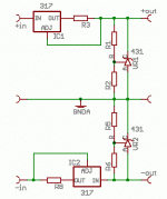
A good temp stable little device with 3 pins in TO92 ( or in SO8 )
that can give you adjustable voltage of 2.5 - 36 Volt.
Isn't this fantastic!
")
lineup
lineup said:
Yes, I buy that, HBarske.
Looks better than only LM317, LM337,
but still very simple and easy to build.
For anyone.
You know my tutor, Nelson Pass,
whenever he uses a voltage regulator for his amplifiers,
he prefers shunt before series regulation.
( LM317/337 are series regulators, while TL431 is a shunt diode )
And so do I.
This is why I love the many possibilities by using TL431
and sometimes in comb with bypass transistors
if need more current/power output.
A good temp stable little device with 3 pins in TO92 ( or in SO8 )
that can give you adjustable voltage of 2.5 - 36 Volt.
Isn't this fantastic!
lineup
Very interesting! Is it any good compared to a good serie regulatator or is there an shunt regulator that is easy to build with better performance? Many times the size is an issue when replacing old LM78XX in exicitning cuircuit! Meaning they must fit into exicting player...
karvid said:
Very interesting! Is it any good compared to a good serie regulatator or is there an shunt regulator that is easy to build with better performance? Many times the size is an issue when replacing old LM78XX in exicitning cuircuit! Meaning they must fit into exicting player...
The one thing you should know
is that using shunt, like TL431
as the only regulation, like in HBarske circuit,
.. is that it, like using normal zener diodes,
is NOT suitable when you need very much current
and the drawn current can variate a lot.
But in this case, the RIAA, it works in Class A
at only like 6 mA per channel.
And as most know, a true Class A draws same amount of current
whatever power or voltage output.
It is 100% constant current taken via and from the regulator.
This makes a true shunt, like TL431 be perfect for regulate this BC550C phono amplifier.
For higher currents and in normal Class AB amplifiers or in chip Op-Amp amps
where current consumption variates depending of how much power output
TL431 is best used with a bypass transistor, to amplify currents.
lineup
RIAA phono riaa preamplifier MM BC550C BC560C Version 2
Great layout!
As far as I can see.
It is not the most simple circuit to design a PCB for.
With all them transistors .....
Now, this was Version 1, from my first post.
If you could update to my Version 2.
In this post:
http://www.diyaudio.com/forums/showthread.php?postid=1072254#post1072254
... and as you see from my comments,
has been a new feature with two 1N4148 diodes
and one small Multi Turn trim potentiometer
for offset adjustment.
And if you read my comments further R17 has been removed.
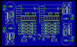
HBarske said:Just a quick shot to see how this might turn out.
We have:
- two channels
- board size: 109 x 63 mm
- seperate regs as shown above for each channel
- added pass transistors to the tl431 for more dissipation
This is how it looks right now:
Great layout!
As far as I can see.
It is not the most simple circuit to design a PCB for.
With all them transistors .....
Now, this was Version 1, from my first post.
If you could update to my Version 2.
In this post:
http://www.diyaudio.com/forums/showthread.php?postid=1072254#post1072254
... and as you see from my comments,
has been a new feature with two 1N4148 diodes
and one small Multi Turn trim potentiometer
for offset adjustment.
And if you read my comments further R17 has been removed.
Okay, I will add those modifications.
Some PSU dimensioning thoughts:
The amplifier is normally rum at +/- 15 Volts, IIRC.
Let's assume the output stage is run at, as you said, 5 mA. So I think we won't have more than 10 mA overall current consumption.
Let's further assume we drive that thing from 2 x 18 V transformer secondaries, then we would have perhaps 22 V unregulated DC voltage.
Let's say we set the CCS to 30 mA, that's three times the maximum load current, certainly enough headroom. The LM 317 drops 1,25 V on the setting resistor, so we need 41,6 R - let's say 39 R, easier to get. This gives us a constant current of 32 mA and a dissipation of 40 mW, no problem for a small resistor.
Under worst case condition (output shorted, likely to happen at turn on) the LM317 dissipates 22 V x 32 mA = 0,7 W. A bit too much for a TO92 device, that's why I went for the TO220 type.
Worst case condidition for the shunt reg is an unloaded output, because it has to dissipate all the energy from the CCS. So maximum energy to get rid of is everything the CCS can deliver, somewhat less than the 0,7 W from above (less due to the voltage losses on the CCS). Also a bit hard for a TO92 device, that's why I added the power transistor to the TL431.
Transformer has to deliver 2 x 18 V @ 32 mA, what sums up to a little more than 1 VA, 2 or 3 VA with some safety margin. More is not useful due to the constant current consumption of the circuit.
Might result in decent and dirt cheap solution.
HBarske said:Okay, I will add those modifications.
Some PSU dimensioning thoughts:
The amplifier is normally rum at +/- 15 Volts, IIRC.
Let's assume the output stage is run at, as you said, 5 mA. So I think we won't have more than 10 mA overall current consumption.
Let's further assume we drive that thing from 2 x 18 V transformer secondaries, then we would have perhaps 22 V unregulated DC voltage.
Let's say we set the CCS to 30 mA, that's three times the maximum load current, certainly enough headroom. The LM 317 drops 1,25 V on the setting resistor, so we need 41,6 R - let's say 39 R, easier to get. This gives us a constant current of 32 mA and a dissipation of 40 mW, no problem for a small resistor.
Under worst case condition (output shorted, likely to happen at turn on) the LM317 dissipates 22 V x 32 mA = 0,7 W. A bit too much for a TO92 device, that's why I went for the TO220 type.
Worst case condidition for the shunt reg is an unloaded output, because it has to dissipate all the energy from the CCS. So maximum energy to get rid of is everything the CCS can deliver, somewhat less than the 0,7 W from above (less due to the voltage losses on the CCS). Also a bit hard for a TO92 device, that's why I added the power transistor to the TL431.
Transformer has to deliver 2 x 18 V @ 32 mA, what sums up to a little more than 1 VA, 2 or 3 VA with some safety margin. More is not useful due to the constant current consumption of the circuit.
Might result in decent and dirt cheap solution.
Yes, we use TO220 LM317T,
they are easier to find, also, than LM317L.
About transformer.
Earlier I told, we need only like 0.100A trafo,
to supply BOTH left and right channel.
But when consumption now will be 2x32 mA ( two LM317 and two LM337, for stereo )
I will recommend a transformer with 0.200 A, minimum.
2x18VAC and 0.2A gives transformer rating should be >= 7.2 VA.
One 10 VA, 2x18 would be easy to find and be perfect here, in my opinion.
Does not matter if is small toroid trafo or a normal small square one.
----------------
This transformer would not drop much from 1.4 x 18 volt.
Will deliver like +- 25 VDC unregulated.
Depending of transformer brand this may actually be ~24-27 VDC.
----------------
You say:
Worst case condition for the TL431 shunt diode is an unloaded output,
because it has to dissipate all the energy from the CCS.
True, but this only if using regulator WITHOUT any amplifier connected to supply.
But 5-6 mA less is nothing, giving still 26-27 mA in TL431.
OK, people do things we we do not expect.
This is why software debugging is so important, having normal people as test users.
They can try to enter whatever into a <FORM>.
Things that the designer is not 'stupid enough' to try.
So, we will design to make supply survive worst case, without load connected.
Very good working, HBarske!
Thanks very much.
lineup
Hi Lineup,
There are a number of ClassA topologies.
All push pull and all but one of the single-ended modulate the supply rail currents.
The one exception that truly draws constant current is utilised very rarely.
Please do not repeat this tripe again. Some folk might think it's true.
totally wrong.And as most know, a true Class A draws same amount of current whatever power or voltage output. It is 100% constant current taken via and from the regulator
There are a number of ClassA topologies.
All push pull and all but one of the single-ended modulate the supply rail currents.
The one exception that truly draws constant current is utilised very rarely.
Please do not repeat this tripe again. Some folk might think it's true.
reply to critics of one detail in one post - slightly off topic here
I repeat whatever I like, for your information.
I have seen more stupid postings than this
even from you, AndrewT.
What the supply see when feeding a true Class A,
is a constant load.
Even if it is, like you say, modulated by eventual output.
Capacitor stores energy within amplifier and after the supply
this reduces some of the modulation seen from power supply.
Still this fact remain valid, although modulated by AndrewT, very correctly, thanks:
The average current drawn from any circuit called Class A, in the very sense of this expression,
is CONSTANT CURRENT.
If it ain't a very constant loading for Power supply - it ain't Class A.
Simply.
And this was what I wanted to tell about.
If you read me right.
No regards, this time
to this slightly off topic post with a slightly unpleasant tone
sincerely december 2006
Lineup Audio Lab
smart but simple amplifier solutions
------------------------------------------
If you like to contribute here, in my topic, AndrewT
you are very welcome as anyone else
if you can add something useful for us
which remains to see .......
AndrewT said:Hi Lineup, totally wrong.
There are a number of Class A topologies.
All push pull and all but one of the single-ended modulate the supply rail currents.
The one exception that truly draws constant current is utilised very rarely.
Please do not repeat this tripe again. Some folk might think it's true.
I repeat whatever I like, for your information.
I have seen more stupid postings than this
even from you, AndrewT.
What the supply see when feeding a true Class A,
is a constant load.
Even if it is, like you say, modulated by eventual output.
Capacitor stores energy within amplifier and after the supply
this reduces some of the modulation seen from power supply.
Still this fact remain valid, although modulated by AndrewT, very correctly, thanks:
The average current drawn from any circuit called Class A, in the very sense of this expression,
is CONSTANT CURRENT.
If it ain't a very constant loading for Power supply - it ain't Class A.
Simply.
And this was what I wanted to tell about.
If you read me right.
No regards, this time
to this slightly off topic post with a slightly unpleasant tone
sincerely december 2006
Lineup Audio Lab
smart but simple amplifier solutions
------------------------------------------
If you like to contribute here, in my topic, AndrewT
you are very welcome as anyone else
if you can add something useful for us
which remains to see .......
Hi Lineup,
you're still wrong.
It is not constant current. Except for that one single-ended topology.
ClassA supply rails vary their current draw as the output draws current.
While the ClassA amp is idling the supply is constant current. Send some current to the load and the supply rail current changes.
If it's dual polarity with a push pull topology then both supply rails change current to allow the output to be driven.
and that's wrong as well.If it ain't a very constant loading for Power supply - it ain't Class A.
Boys stop this PLEASE! Not that way!
Holger, you have been listening to a lot of phono amps, a lot more than I did for shure. Do you have any exeriences with schematics like this one. Except for the trick with the parallel transistors, it is a quite simple schematic which has a lot of charme. But is it really capable to compete with a midrange opamp (opa2132 e.g.) in a "state of the art" schematic, like the one Thorsten presented with the Analogue Addicts?
I'm not shure.
Best regards
Floric
Hi Floric,
to be honest: I have no clue if this one can cope with a good OP circuit. I never listened to this circuit.
This is a nearly 25 year old Elektor project and I like it for it's simplicity, and simple things sometimes just sound better.
It has even been marketed in Germany (without the author's permission, I am sure) and many people report it sounds good.
You can build this one for 20€, and that's a quality of it's own.
so much for saying something is constant
Yes, as I told and even changed to expression average power supply loading,
I did agree, too.
Back to this circuit and the suggested clever power supply
using LM317 for CCS and feeding a precise shunt regulation.
I did some estimation of my actually circuit
with expected output voltage
(1mV rms from average pickup??? gives 100mV rms out)
into a normal average load (10kohm ??).
The output current variations (modulation)
is only a few uA by my Low Noise BC550C circuit.
( 14uA out = 7uA variation in each push pull output transistor )
gives a modulation dept of our shunt regulator of what ..
...... fractions of a % !!!
So, in this very case, which I had in mind, when posting,
and if we also would add some suitable power supply rails bypass capacitors,
we do not have to feel bad saying the power supply see a 'constant load'.
In fact what we call constant
in an audio amplifier at work
is only constant by our definition.
Even most advanced CCS we can think of, as well as more simple ones,
can and WILL HAVE slight variations in current delivered to rest of circuit.
When audio amplifier is processing, even small voltages/currents.
lineup
HBarske said:Forgot to say: Andrew's of course right on the Class A current draw thing, but that's indeed another story and doesn't belong here.
Yes, as I told and even changed to expression average power supply loading,
I did agree, too.
Back to this circuit and the suggested clever power supply
using LM317 for CCS and feeding a precise shunt regulation.
I did some estimation of my actually circuit
with expected output voltage
(1mV rms from average pickup??? gives 100mV rms out)
into a normal average load (10kohm ??).
The output current variations (modulation)
is only a few uA by my Low Noise BC550C circuit.
( 14uA out = 7uA variation in each push pull output transistor )
gives a modulation dept of our shunt regulator of what ..
...... fractions of a % !!!
So, in this very case, which I had in mind, when posting,
and if we also would add some suitable power supply rails bypass capacitors,
we do not have to feel bad saying the power supply see a 'constant load'.
In fact what we call constant
in an audio amplifier at work
is only constant by our definition.
Even most advanced CCS we can think of, as well as more simple ones,
can and WILL HAVE slight variations in current delivered to rest of circuit.
When audio amplifier is processing, even small voltages/currents.
lineup
Re: RIAA phono riaa preamplifier MM BC550C BC560C Version 2
HBarske
The PCB for version 2
you said you would do - have you done this layout?
See my Post #16 for schematic.
Regards & Christmas
lineup
lineup said:
Great layout!
As far as I can see.
It is not the most simple circuit to design a PCB for.
With all them transistors .....
Now, this was Version 1, from my first post.
If you could update to my Version 2.
In this post:
http://www.diyaudio.com/forums/showthread.php?postid=1072254#post1072254
... and as you see from my comments,
has been a new feature with two 1N4148 diodes
and one small Multi Turn trim potentiometer
for offset adjustment.
And if you read my comments further R17 has been removed.
HBarske
The PCB for version 2
you said you would do - have you done this layout?
See my Post #16 for schematic.
Regards & Christmas
lineup
HBarske said:Just a quick shot to see how this might turn out.
We have:
- two channels
- board size: 109 x 63 mm
- seperate regs as shown above for each channel
- added pass transistors to the tl431 for more dissipation
This is how it looks right now:
HBarske said:Okay, I will add those modifications.
Some PSU dimensioning thoughts:
The amplifier is normally rum at +/- 15 Volts, IIRC.
Let's assume the output stage is run at, as you said, 5 mA. So I think we won't have more than 10 mA overall current consumption.
Holger, HBarske
you said you would make new layout of version 2:
Okay, I will add those modifications.
I am waiting ..
This low noise riaa
is easy to build - opamp style with common transistors
and will have very great performance - if my sims are somewhat correct.
I think a good PCB prototype silksheet
would be of interest and use for many 'Analogue people'.
- Status
- This old topic is closed. If you want to reopen this topic, contact a moderator using the "Report Post" button.
- Home
- Source & Line
- Analogue Source
- BC550 BC560 Very low noise RIAA