valveitude said:Thank you for the response Mr. badman, in spite of the considerable volume of views of this thread, I've had very few comments...kind of a lonely fishbowl feeling here.
This is a fascinating thread with great pictures - your work is starting to look very impressive

Hi neutron7,
Boy, you read my beads
Thats where the real mods come in. The bearings in a drill press quill aren't strong enough to handle the lateral forces of milling, but there isn't room for bigger ones. So, I did the next best thing, I turned out the quill to fit a stack of bearings. I have a stack of 3 on the bottom (cutting end) and a stack of 2 on top. I also re-cut the taper on the end to move it as close as possible to the bearing race to minimize spindle flex. The biggest (and most difficult) improvement was making a custom collet chuck to fit the spindle's Jacobs 33 taper. I also secured it by the column to the shop wall. It aint no Bridgeport, but I can cut .05" a pass in aluminum and .02" a pass in steel with a 1/2" end mill. Slow and steady is the name of the game with it.
Thank you.
Hello Ropie,
Thats some skin condition you have there
Thank you..I will definitely keep up the progress posting.
Casey
Did you get a big ol floor standing drill press and put on an ebay chinese slide table to make it a milling machine?
Boy, you read my beads
apply too much side force it "jumps" up and sideways, almost as if the 2 main bearings are not preloaded properly. can they even be adjusted?
Thats where the real mods come in. The bearings in a drill press quill aren't strong enough to handle the lateral forces of milling, but there isn't room for bigger ones. So, I did the next best thing, I turned out the quill to fit a stack of bearings. I have a stack of 3 on the bottom (cutting end) and a stack of 2 on top. I also re-cut the taper on the end to move it as close as possible to the bearing race to minimize spindle flex. The biggest (and most difficult) improvement was making a custom collet chuck to fit the spindle's Jacobs 33 taper. I also secured it by the column to the shop wall. It aint no Bridgeport, but I can cut .05" a pass in aluminum and .02" a pass in steel with a 1/2" end mill. Slow and steady is the name of the game with it.
thats beutiful work by the way
Thank you.
Hello Ropie,
Thats some skin condition you have there
This is a fascinating thread with great pictures - your work is starting to look very impressive
Thank you..I will definitely keep up the progress posting.
Casey
valveitude said:
Hello Ropie,
Thats some skin condition you have there
That's what happens when you think that acid is as Safe As Milk for drinking.
Oh, and nice work on the platter.
Max
Nice work. I have a Teres from a kit, with a few mods to allow easy adjustment of arm height. I've been thinking of trying a
DIY linear tracker but have to finish some speakers and amps first.
The most interesting thing is your tooling. I thought I was the only one who cobbled together that kind of stuff - though not on that scale yet. I'da probabaly taken it to a friend with a brake drum lathe and figured out a way to use that. Or worse, mounted a belt sander vertically and true the edge against it. Appalling huh?
Sheldon
I was following your transformer core material thread and found your link to the turntable project. You must have more patience than one thousand men to do the kind of work you are doing.
I am sure the results will be more than worth the effort you have expended so far. I will follow this thread until it is concluded. I had thought to build a turntable and have done some modest stuff with AR-XA and the like, but this is of a whole other caliber! Great stuff!
Kevin
I am sure the results will be more than worth the effort you have expended so far. I will follow this thread until it is concluded. I had thought to build a turntable and have done some modest stuff with AR-XA and the like, but this is of a whole other caliber! Great stuff!
Kevin
Thanx for all the encouragement guys!!
I feel kind of embarrassed now with my “lonely fishbowl” comment , I guess it was paranoia not knowing if the viewers of this thread were silently chuckling or cheering…I should have known better.
Tooling has, and always will be (until the Star Trek replicator becomes a reality anyway) the bane of the diy’ers existence. I lost count a long time ago of the number of ideas/projects that I discarded because I “thought” I needed something I didn’t have. About 10 or so years ago after one such point, I decided that my next project would be a metal shop. Well years later I still don’t have the shop I dreamed of, but I also have the knowledge that I don’t necessarily need it. Oh sure, more tooling would make things easier and quicker, and on the occasion I simply can’t do without, I make what I need. And so another tool goes into the collection ( I have a dandy set of drum sanders now for example). Here is a thought to consider, in the 1800’s the machinists of the day (they were called “mechanics” then) entire collection of tools consisted of chisels, files, and scrapers. No kidding. Luxuries like lathes and mill machines were reserved for the factory floors. A case in point that most can relate to, is the engine in the Wright brothers first successful plane. Their “mechanic” built it from scratch and chiseled the crank shaft out of a solid plate of steel!! Look it up.
Only if the results were. I actually eyed the belt sander for a while before I settled on my drum idea.
Well, I will actually finish this project..patience is without a doubt the most important tool I have. It wasn’t always this way..working with metal taught it to me.
Thanx again for all the encouragement guys…I should have another progress report after this weekend .
Casey
I feel kind of embarrassed now with my “lonely fishbowl” comment , I guess it was paranoia not knowing if the viewers of this thread were silently chuckling or cheering…I should have known better.
The most interesting thing is your tooling. I thought I was the only one who cobbled together that kind of stuff
Tooling has, and always will be (until the Star Trek replicator becomes a reality anyway) the bane of the diy’ers existence. I lost count a long time ago of the number of ideas/projects that I discarded because I “thought” I needed something I didn’t have. About 10 or so years ago after one such point, I decided that my next project would be a metal shop. Well years later I still don’t have the shop I dreamed of, but I also have the knowledge that I don’t necessarily need it. Oh sure, more tooling would make things easier and quicker, and on the occasion I simply can’t do without, I make what I need. And so another tool goes into the collection ( I have a dandy set of drum sanders now for example). Here is a thought to consider, in the 1800’s the machinists of the day (they were called “mechanics” then) entire collection of tools consisted of chisels, files, and scrapers. No kidding. Luxuries like lathes and mill machines were reserved for the factory floors. A case in point that most can relate to, is the engine in the Wright brothers first successful plane. Their “mechanic” built it from scratch and chiseled the crank shaft out of a solid plate of steel!! Look it up.
I'da probabaly taken it to a friend with a brake drum lathe and figured out a way to use that. Or worse, mounted a belt sander vertically and true the edge against it. Appalling huh?
Only if the results were. I actually eyed the belt sander for a while before I settled on my drum idea.
I was following your transformer core material thread and found your link to the turntable project. You must have more patience than one thousand men to do the kind of work you are doing.
Well, I will actually finish this project..patience is without a doubt the most important tool I have. It wasn’t always this way..working with metal taught it to me.
Thanx again for all the encouragement guys…I should have another progress report after this weekend .
Casey
valveitude said:I decided that my next project would be a metal shop. Well years later I still don’t have the shop I dreamed of, but I also have the knowledge that I don’t necessarily need it.
Casey
But maybe it is available. When I went to high school, all the schools had metal shop, woodshop, autoshop, etc.. Some years ago, I wanted to build a childrens bed and cut the wood to make a guitar. I took an adult school woodshop course, in which the formal instruction consisted of; "I'll be over here if you need any help with any of the tools, work safely". The shop was fully equiped with saws, lathes, joiners, power planers, etc.. The vocational courses are no longer available in many areas, but maybe that still exists in your area.
Sheldon
The vocational courses are no longer available in many areas, but maybe that still exists in your area.
If only it were so. After this weekend, I would put a high premium on access to a more equipped shop. Of all the work on this table so far, this last couple of days has been the least enjoyable.
I decided to change course a bit , and work on my plinths. First I laminated the bottom plinth, so far so good, then I set out to dimension my top plinth. I made a jig to fit the spindle mount hole in the plinth…
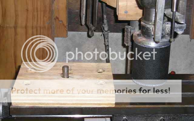
… all set to go..and go..and go. News flash…aircraft aluminum is a wee bit more tenacious than Corian. Couple that with the fact that I generously oversized the rough cuts , and a good time ensued…
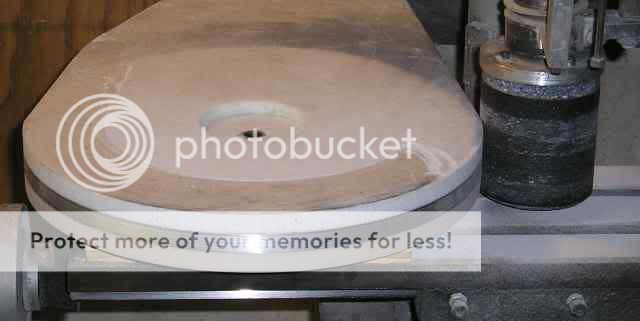
…1/8” doesn’t sound like much, until your removing it .003” at a time, the max cut the paper can handle without disintegrating. After getting the radius down, I proceeded on to the straight cuts…
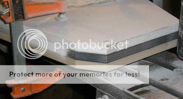
…all is not in vain however. It looks quite nice…
… I intend on leaving the brushed aluminum exposed, I will veneer over the Corian. I figure I put around 20 hours this weekend standing in front of my press cranking handles on the x-y table, in addition, I changed the paper on the sanding drum 21 times. Would I do it again …you bet I would!! In fact I’ll be working on the bottom plinth next. This time however, I will use my die grinder to cut it just shy of the final diminsion..should speed things considerably.
Casey
Amazing what a goods night rest and some aspirin can do for your attitude When I wrote the above post, I had just come in from a 2 (long) day battle and was sore and tired. I just gave my plinth the once over with a fresh outlook, and I gotta say it is nice, the brushed aluminum center rocks …definitely worth the effort.
Tonight I drilled an alignment hole in the bottom plinth, set a piece of rod in it and sat the top plinth over it. I then scribed a line around the top plinth to the bottom one. I will now remove the bulk of the excess before I set up the sanding drum. How? I’m not sure yet, bench grinder or die grinder maybe. This will save me a LOT of time on this go round.
I’ll keep ya posted,
Casey
When I wrote the above post, I had just come in from a 2 (long) day battle and was sore and tired. I just gave my plinth the once over with a fresh outlook, and I gotta say it is nice, the brushed aluminum center rocks …definitely worth the effort.Tonight I drilled an alignment hole in the bottom plinth, set a piece of rod in it and sat the top plinth over it. I then scribed a line around the top plinth to the bottom one. I will now remove the bulk of the excess before I set up the sanding drum. How? I’m not sure yet, bench grinder or die grinder maybe. This will save me a LOT of time on this go round.
I’ll keep ya posted,
Casey
mpm32 said:Why not use a router? I've used a router on aluminum successfully before.
Second that. Spiral bit works well.
Sheldon
Why not use a router? I've used a router on aluminum successfully before.
Second that. Spiral bit works well.
Stellar idea Gents!! I hope I can find a bit with a 1 1/2" long flute (the thickness of the plinth), otherwise I guess I'll have to cut from both sides.
Looks like I'm heading for the hardware store today.
Casey
A bit of a setback that led to an improvement.
I was sitting in the shop contemplating my next move. Looking at the plinth, thinking about how I would veneer it, I noticed a small black line between the top Corian and the lead towards the back. I got off of my stool to take a closer look…my stomach dropped. The lamination had partially separated. I immediately inspected the rest of the pieces, and found no problems. In fact, the only part of the plinth that did separate, was on the top Corian surrounding what I had thought was a hairline crack of no consequence. Clearly this crack was in fact a full blown fracture in the top piece. The combination of the sanding vibration and the cold/warm cycling of the shop temp. had caused it to separate on both sides of the crack, fortunately I caught it before it fully de-laminated.
After several minutes of colorful superlatives, I considered my options and decided to go ahead with an approach I had considered originally, but thought would be to labor intensive….
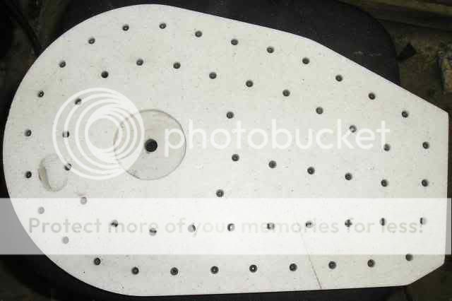
… what you see here is 56 1” 8-32 socket head cap screws stitching the whole thing together. You can see the crack on the lower right. The blemish on the left is the results of having a drill bit break. I was able (eventually) to remove the bit, but the punch I used to push the bit through a hole I drilled on the bottom mushroomed. When I drove the punch out with yet another punch, it blew a chunk of the Corian out with it. I epoxied the piece back on, and after it cured re-drilled. This job wasn’t as bad as I first thought it would be with one notable exception…DRILLING!! I thought the biggest job would be the tapping. Corian, lead, epoxy, and lead are all notorious for loading up a drill bit, put the four together and you have a major PITA! I found myself cleaning out the drill flutes with a carbide scribe 2-3 times per hole.
I feel the whole thing was worth it though. Not only is the Corian sucked up tight again, but the rigidity of the whole thing is at least an order of magnitude better, yet its still very acoustically dead. I haven’t decided if I will do the bottom plinth yet, but I will probably talk myself into it.
Now, where was I?…..
I was sitting in the shop contemplating my next move. Looking at the plinth, thinking about how I would veneer it, I noticed a small black line between the top Corian and the lead towards the back. I got off of my stool to take a closer look…my stomach dropped. The lamination had partially separated. I immediately inspected the rest of the pieces, and found no problems. In fact, the only part of the plinth that did separate, was on the top Corian surrounding what I had thought was a hairline crack of no consequence. Clearly this crack was in fact a full blown fracture in the top piece. The combination of the sanding vibration and the cold/warm cycling of the shop temp. had caused it to separate on both sides of the crack, fortunately I caught it before it fully de-laminated.
After several minutes of colorful superlatives, I considered my options and decided to go ahead with an approach I had considered originally, but thought would be to labor intensive….
… what you see here is 56 1” 8-32 socket head cap screws stitching the whole thing together. You can see the crack on the lower right. The blemish on the left is the results of having a drill bit break. I was able (eventually) to remove the bit, but the punch I used to push the bit through a hole I drilled on the bottom mushroomed. When I drove the punch out with yet another punch, it blew a chunk of the Corian out with it. I epoxied the piece back on, and after it cured re-drilled. This job wasn’t as bad as I first thought it would be with one notable exception…DRILLING!! I thought the biggest job would be the tapping. Corian, lead, epoxy, and lead are all notorious for loading up a drill bit, put the four together and you have a major PITA! I found myself cleaning out the drill flutes with a carbide scribe 2-3 times per hole.
I feel the whole thing was worth it though. Not only is the Corian sucked up tight again, but the rigidity of the whole thing is at least an order of magnitude better, yet its still very acoustically dead. I haven’t decided if I will do the bottom plinth yet, but I will probably talk myself into it.
Now, where was I?…..
I started the weekend by filling in the screw heads from the cap screws in the top plinth, and roughed in the bottom plinth with a router and a carbide bit (thanx again for the idea mpm32 ), the rest of my time was spent on the motor….
…like a lot of people, I’ve been debating between DC (quite operation and easy supply), and AC (speed locks on frequency). After going back and forth, I decided if I could make a quite AC motor assembly, the potential speed accuracy would be worth the effort. I intend on building a frequency switchable Wien Bridge power source for it.
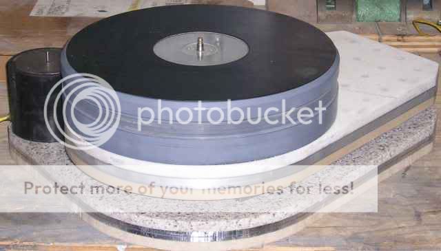
I started out by making a mounting plate out of ¼” steel. I mounted it to a piece of ABS pipe by running a bead of silicon glue around the inside edge, and placing it over the mounting plate. The mounting plate is slightly undersized, leaving a small gap for the silicon to fill. The plate is essentially suspended by a thin rubber ring…
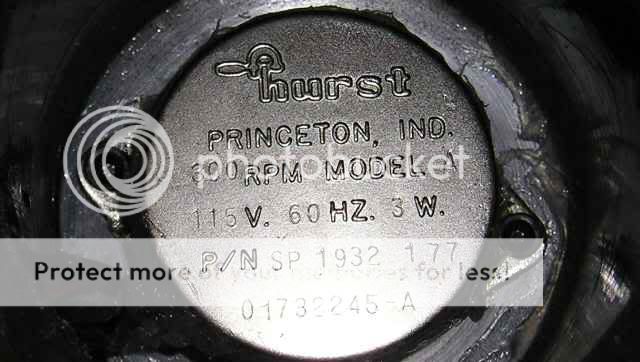
… I then mounted my motor, a 3W 300 rpm Hurst from an old Harmon Kardon table. I had completely sealed the unit in silicon glue earlier…

…Why seal up the motor ? So it would survive me doing this…

…I filled up the case with iron powder left over from my transformer experiments . After vibrating , and tamping it down, I sealed it up with an aluminum disc epoxied in place. In addition to the obvious sound dampening, it also acts as a mondo magnetic and electric field shield, as well as a ballast. I would guess the weight at around 10 lbs.
How quite is it?…BWHAA-HA-HA_HA…sitting on a piece of 1/32” thick dense cell foam I plan on using for an anti-skid surface on the bottom, you have to put your ear ON it to hear the hum. Even then, the miniscule noise of a 1/8” shaft turning in a lubed bronze bushing is equally loud
Next I’ll be working on my pulley, I really have a need to see it spinning under its own power .
Casey
…like a lot of people, I’ve been debating between DC (quite operation and easy supply), and AC (speed locks on frequency). After going back and forth, I decided if I could make a quite AC motor assembly, the potential speed accuracy would be worth the effort. I intend on building a frequency switchable Wien Bridge power source for it.
I started out by making a mounting plate out of ¼” steel. I mounted it to a piece of ABS pipe by running a bead of silicon glue around the inside edge, and placing it over the mounting plate. The mounting plate is slightly undersized, leaving a small gap for the silicon to fill. The plate is essentially suspended by a thin rubber ring…
… I then mounted my motor, a 3W 300 rpm Hurst from an old Harmon Kardon table. I had completely sealed the unit in silicon glue earlier…
…Why seal up the motor ? So it would survive me doing this…
…I filled up the case with iron powder left over from my transformer experiments . After vibrating , and tamping it down, I sealed it up with an aluminum disc epoxied in place. In addition to the obvious sound dampening, it also acts as a mondo magnetic and electric field shield, as well as a ballast. I would guess the weight at around 10 lbs.
How quite is it?…BWHAA-HA-HA_HA…sitting on a piece of 1/32” thick dense cell foam I plan on using for an anti-skid surface on the bottom, you have to put your ear ON it to hear the hum. Even then, the miniscule noise of a 1/8” shaft turning in a lubed bronze bushing is equally loud
Next I’ll be working on my pulley, I really have a need to see it spinning under its own power .
Casey
Lookin' good!!
Thank you.
Does the Hurst have any sort of thrust bearing on the bottom of the shaft?
It has a thust bearing, but not at the bottom. A brass washer is pressed about a 5/8" down from the top, this rides on a washer of some stiff synthetic material ,that in turn, rides on the brass bushing in the motor. The "cup" magnet is pressed on from the bottom with the same style washer, sandwiching the bushing between it and the top washer(s). Basically, the magnet "hangs" from the top washer.
Hurst still makes the motor, you can see it here..its the first one on the list...
http://www.myhurst.com/hurstmfg/qseries.jsp?series=Series+A,+AB+Direct+Drive+Synchronous+Motor
Casey
Another weekend in the shop…this time however, it was a 2 step forward - 3 steps back situation.
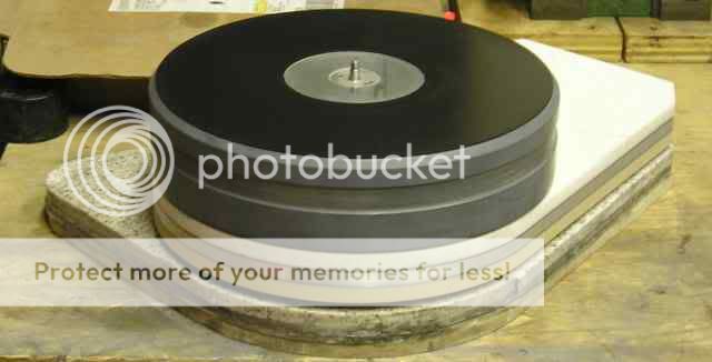
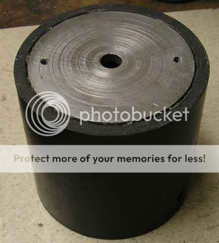
Well yes..with no load. And then this only applies to the stationary bits, not the armature. Playing around with the spinning motor, I noticed that when I put a load on the motor by pinching the spinning shaft, the overall noise increased slightly, but more importantly, the shaft vibrated a bunch. Left unchecked, I felt that this would buzz the heck out of the Mylar tape belt. I set out to make a harmonic balancer/flywheel pulley assembly. I constructed a copper/lead laminate wheel and built the pulley assembly you see here sitting next to the motor….

… It did virtually eliminate the shaft vibration, it also however loaded the motor considerably. The weight (around 8 oz.) was to much of a vertical load for the motor, pushing on the brass washer that the armature hangs from. It increased the motor noise to a point of being able to here it a couple feet away…this will not do. I then made a conventional pulley to see how big a problem the vibrating shaft was. It’s big. Running the table with the pulley shown on the motor, sets up a vibration on the belt strong enough that you can actually see it…this also will not do.
So, a heavy pulley assembly acts as a harmonic balancer, killing shaft vibration, but increases motor noise. A light pulley doesn’t raise the noise of the motor significantly, but leaves the shaft vibration unchecked, which in turn, vibrates the heck out of the belt.
My next attempt will be a hydraulic dampener of some sort. The ideal fluid ( to my mind anyway) would be mercury, but being hazardous would require extra care to make sure its sealed. Second choice would be a heavy oil. I will probably try oil first.
Another thing that became painfully obvious playing with the belt drive, is how freakin’ critical alignment is. I found that tilting the motor a couple thousandths of an inch with shims would cause the belt to “walk” up or down the pulley/belt groove. I believe the larger diameter of my low rpm pulley exasperates this problem relative to a high rpm setup running the belt directly on the motor shaft. So, I will be modifying my motor mount, and plinth, to accommodate a fine level adjustment.
This weekend will go into the “learning curve” category.
If anybody has some pulley noise dampener ideas, I’m all ears.
Casey
How quite is it?…BWHAA-HA-HA_HA…sitting on a piece of 1/32” thick dense cell foam I plan on using for an anti-skid surface on the bottom, you have to put your ear ON it to hear the hum. Even then, the miniscule noise of a 1/8” shaft turning in a lubed bronze bushing is equally loud
Well yes..with no load. And then this only applies to the stationary bits, not the armature. Playing around with the spinning motor, I noticed that when I put a load on the motor by pinching the spinning shaft, the overall noise increased slightly, but more importantly, the shaft vibrated a bunch. Left unchecked, I felt that this would buzz the heck out of the Mylar tape belt. I set out to make a harmonic balancer/flywheel pulley assembly. I constructed a copper/lead laminate wheel and built the pulley assembly you see here sitting next to the motor….
… It did virtually eliminate the shaft vibration, it also however loaded the motor considerably. The weight (around 8 oz.) was to much of a vertical load for the motor, pushing on the brass washer that the armature hangs from. It increased the motor noise to a point of being able to here it a couple feet away…this will not do. I then made a conventional pulley to see how big a problem the vibrating shaft was. It’s big. Running the table with the pulley shown on the motor, sets up a vibration on the belt strong enough that you can actually see it…this also will not do.
So, a heavy pulley assembly acts as a harmonic balancer, killing shaft vibration, but increases motor noise. A light pulley doesn’t raise the noise of the motor significantly, but leaves the shaft vibration unchecked, which in turn, vibrates the heck out of the belt.
My next attempt will be a hydraulic dampener of some sort. The ideal fluid ( to my mind anyway) would be mercury, but being hazardous would require extra care to make sure its sealed. Second choice would be a heavy oil. I will probably try oil first.
Another thing that became painfully obvious playing with the belt drive, is how freakin’ critical alignment is. I found that tilting the motor a couple thousandths of an inch with shims would cause the belt to “walk” up or down the pulley/belt groove. I believe the larger diameter of my low rpm pulley exasperates this problem relative to a high rpm setup running the belt directly on the motor shaft. So, I will be modifying my motor mount, and plinth, to accommodate a fine level adjustment.
This weekend will go into the “learning curve” category.
If anybody has some pulley noise dampener ideas, I’m all ears.
Casey
- Status
- This old topic is closed. If you want to reopen this topic, contact a moderator using the "Report Post" button.
- Home
- Source & Line
- Analogue Source
- Corian Turntable Fun