
6072a said:Hi Everyone,
Can anyone help with the component values for the Linn Valhalla ?
What values have R33,C5,C21?
Regards Alex
I have the diagram without component values.
On my board the values are:
R33 = 180k
C5 = 220pF? (red-red-blk-gold-blk)
C21 = 3.3nF? (orn-orn-red-silv-gold)
One upgrade you might try when repaired is to upgrade the 47uF 250V ( 0r 200V in some ) to 220uF. It seems not to cause any problems and reduces hum by about 6dB or better ( see graphs ). One can not see this hum usually as it is close to the 50 Hz reference, it will be seen if 60 Hz mains and is about at - 40 dB. There are 3 caps of this type, the two that run across the PCB are prime and see about 320 VDC. When cured the sound is better, wow I guess. Subtle and could be imagined as the belt should deal with this.
One small modificaton that can help is a floating isolated transformer supply ( centre ground worse!). Either 230 or 115VAC will do fine ( set fuse on PCB to suit ). The distortion of the Valhalla is about 0.05%, not bad. Alas how the motor draws current makes that rather unimportant. Nice all the same it works this well. I have tried many mods and these are the ones that work.The displaced graph is how I found this when trying 45 RPM ( best not to as it seems a step too far for ones who tried it ). I put the 220uF in quickly to test with the 47uF Linn fit, just 220uF 250VDC works fine. I tried other modes which gave small returns so not listed. One was a PSU for the oscillator, nice if keeping power use down. Otherwise not worth it.
The larger sound difference is the output voltage. 90VAC( rms ) is about the best as in the early Valhalla. Some play with the blue phase capacitor ( 220nF ). I think voltage more important.
Hi Nigel Pearson,
I am in the process of immortalizing my Valhalla board since I think it is the best way to enjoy a Linn deck, especially since I do not like separate box placed next to the turntable. To this end, I am adding a small 25VA isolation txformer and beefing up all the hot resistors to a much higher wattage as well as considering your 220uF change. I just wanted to make sure I understand this correctly. Are u suggesting all 3 of the 47uF caps changed ? These are the C1 & C2 power supply caps and the C8 which is the motor dc decoupling cap. Is that correct ?
My main challenge at the moment is physical space. I have to find some ingenious ways of squeezing these larger components onto the board.
Thanks
Has anyone generated a low voltage (24 volt) using the Valhalla board ? I am thinking of exchanging the 110 volt premotec/airpax Linn motor with a 24 volt Hurst motor. If I can generate 20 - 24 volts from the Valhalla, I cn drive the Hurst motor. Since it is of lower voltage, it is bound to be a bit less noisy.
Has anyone tried adjusting the Valhalla board to a LOWER voltage ?
Thanks
Has anyone tried adjusting the Valhalla board to a LOWER voltage ?
Thanks
There is a tiny chance it could work. If 20V rms it would be 0.7 watts which for the Airpax motor is about right. As the Valhalla output stage seems to be class A it should either work or not work. If class AB it could go badly wrong. Be sure the new motor input power is about 1/2 watt and not greater than 0.8 watts. Not output power which is far less. Like all of these things it can go badly wrong.
One would need to do two mods. RV1 reset to give 20 Vrms and motor blue phase capacitor increased in value as recomended by maker.
The rub is this. The 115V Airpax is a very good motor. Any noise it has is due to calculations of the designer for output power. If an Airpax was rewound for 24 Vrms it would be identical. Thicker wire, less turns.
Most motor noise seems to come from the triagular motor iron slots inside the motor. The Fourier series for a triangle wave is a squarewave that has been filtered. The first vibration harmonic is 1/9 F3 or a rather unpleasent -19 dB. Through rather nice design Airpax is - 24 dB. There is a very good and a very bad side to this. Good is the motor acts as a filter. Try running the Airpax at 78 rpm ( 585 rpm at motor ) it won't want to. That's the filter effect. Equally the absolute quality of the waveform is not critical and will not help it as long as a better than 5% THD, in theory 10% would be OK if above 200 Hz . Seeing as 0.05% is easy enough one should do that. Most surprising is a triangle wave is no better than a squarewave ( that isn't obvious from theory ). Sine triangle and square need to be different rms voltages to be to be a fair test. Start low and find the least to get it moving first. Sine is a good idea if doing electronic phase shift ( quadrature ). It's a no brainer to use sine.
A Garrard motor ( Lenco, Thorens also ) - 50 dB. Different design with different outcomes.
One of the cheap Chinese 100 watt ( 28 Vrms 8R ) stereo chip amps would drive a 24 Vrms motor. One would design a sine cosine oscillator to drive the phases. It's very likely no heatsink would be required at this low power. Class D seems the wrong way to do it ( I have and it works ), AB would be better. If you really want to do this I have a few design notes. It does involve a bit of study to understand how it works.
I did try a 1.8 degrees stepper motor, the Airpax would be 7.5 degrees. I was very surprised how well it worked. It was very much better on sine waves than the square most often used. It has no iron slots unlike the Aipax. I used 6 Vrms. The pulley is 4.1667 times larger. It had far more torque and comparable vibration. The LP12 belt is too good when vibration.
Hi Nigel Pearson,
I am in the process of immortalizing my Valhalla board since I think it is the best way to enjoy a Linn deck, especially since I do not like separate box placed next to the turntable. To this end, I am adding a small 25VA isolation txformer and beefing up all the hot resistors to a much higher wattage as well as considering your 220uF change. I just wanted to make sure I understand this correctly. Are u suggesting all 3 of the 47uF caps changed ? These are the C1 & C2 power supply caps and the C8 which is the motor dc decoupling cap. Is that correct ?
My main challenge at the moment is physical space. I have to find some ingenious ways of squeezing these larger components onto the board.
Thanks
You might as well because there is no chance of getting it wrong if all three. I had no trouble fitting the parts. Mine are 220uF 250V Nichicon radials 105 C types. I used a sleeve to the wires to make it safe and tidy. They are almost the same size or fit the space. Be sure you get +/- right. I was able to clear the LP12 bottom hardboard cover. C8 is fine as 47 uF if prefered.
If you look at the design it is very well thought out. C1 C2 makes a 23.5 uF > 400 V capacitor ( some were 47 uF 200 VDC, others 250 VDC ). When USA the AC is fed to C1 C2 center to get 294 VDC from 115 VAC.
2 x 220 uF offers 110 uF in total. There is a marginal advanatge using 230 VAC.
The Lingo isn't a dramatically better design.
I meant to ay C18 above, sorry (not C8)....
A question also about Hercules 2 board....
Has anyone used this board and experienced the same heat issues (the two 15k resistors overheating) that Valhalla has suffered from ? I cannot find a hercules schematic anywhere but it "seems" like it is a very similar design at the hi voltage stage. So I am presuming it may suffer the same heat issues.
Anyone has experienced this or any other shortcomings like on the Valhalla board (like the undervoltage specification of the 47uF capacitors and inadequate bridge rectifier) ?
Thanks
I also wish I had found this site before I started any of this stuff:
Frequency Converters Archives - KCC Scientific
Frequency Converters Archives - KCC Scientific
Does anyone have the CURRENT draw requirements for the Valhalla/Hercules boards at 115 volt and 230 volts ? I want to add an isolation txformer and I would like to know to select the correct txformer wattage..
I know the boards are about 13VA or so but does that linearly txlate to proportional currents since there is a voltage doubler on the 115 volt supply.
Thanks
I know the boards are about 13VA or so but does that linearly txlate to proportional currents since there is a voltage doubler on the 115 volt supply.
Thanks
I would like to change the Valhalla (or Hercules) such that the switch acts as a 'standard' series mains power switch and not a latch. I will ONLY use the 33 rpm setting and not interested in 45. How do I change the ribbon cable circuit such that this works ?
Do it the easy way and install a switch in the incoming mains. I wouldn't touch the speed switch.

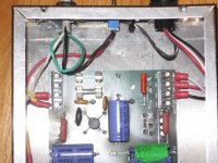
Check out the pic. This is my old Valhalla in an external box. You can see the switch in the center, that cuts power to the board. I'm now using a Hercules, but the connections are the same.
jeff
Attachments
- Status
- This old topic is closed. If you want to reopen this topic, contact a moderator using the "Report Post" button.
- Home
- Source & Line
- Analogue Source
- Linn Valhalla